2 Axis Camera Magnetic Mount for Freenove ESP32-WROVER

Description
PDFThis model lets you mount a Freenove ESP32-WROVER board (buy from their global site or Amazon) in your enclosure and use it to automatically upload images to Prusa Connect.
The mount provides two degrees of freedom to adjust the aim of the camera. It is designed to stick magnetically to the enclosure so you can place it anywhere you want, but you can also use an M3 screw in a free hole in the enclosure. All the parts around the enclosure for the board have cutouts to allow airflow and prevent heat buildup.
UPDATES:
- Updated links since the Freenove board is now supported by the official firmware.
- Added an alternate design of the camera holder with an opening to support larger lenses and a glare shade.
- Added comparison of the view from different lenses
- Added a small crossbar to one of the vent openings so the camera holder insert couldn't fall out.
Hardware
The hardware needed is listed below. The links listed are Amazon affiliate links, but there are many ways to source these parts.
- FreeNove ESP-32 WROVER board - (Amazon)
- comes with the camera module, a USB-C cable, and a 1GB SD card
- Optional - an OV2460 with a wider-angle lens - 21mm x 120 degrees is the one I prefer of the ones tested (AliExpress)
- M3 hardware - (Amazon)
- 3 M3 nuts
- 1 M3x20 socket head screw
- 2 M3x8 socket head screws
- 12 5mm diameter x 3mm thick magnets - (Amazon) - optional.
- If you don't want to use the magnets, you need another M3x8 screw and M3 nut to use one of the mounting holes in the enclosure.
- USB adapter for power - (Amazon) - any adapter will probably do, the power requirements are not very large
Lens Choice
The Freenove board comes with an OV2460 that has a 66 degree lens. This is pretty narrow for the small space, so I bought an OV2460 with a 21mmx120 degree and and 21mmx160 degree lenses to see the differences. Here's a quick comparison:
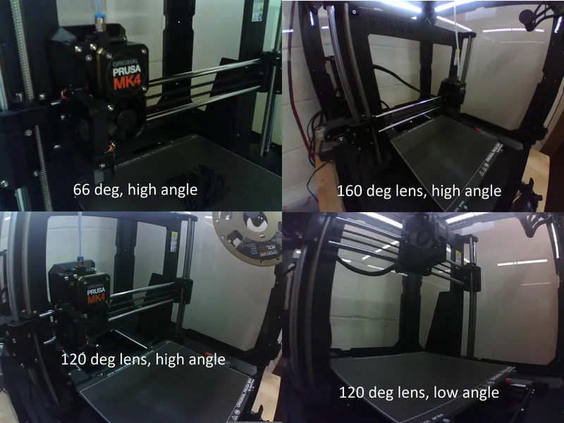
I think the 120 degree lens is probably the best fit. The 120 degree lens with low angle placement (below the cable support at the halfway point of the vertical support) does a reasonable job of seeing the whole print area. The 160 degree lens is really too wide and captures a lot of things outside the area of the print bed. The high angle is necessary for the narrow 66 degree camera, but the wider cameras can be placed lower to make it easier to see small prints that may be hidden by the extruder.
The 120 and 160 degree lenses are much larger, so a modified camera body is needed to make room for the lens to pass through from behind.
Both the 120 and 160 degree lenses pick up glare from the lights in the top of the enclosure, so I added a glare shade that clips into the vent holes in the camera holder. Although the shade is compatible with both the original and wide angle camera holders, it's probably only needed with the wider angle lenses, since the 66 degree lens is too narrow to see the lights while pointed at the printer.
Printing
Files:
- If you are using the stock 66 degree camera:
- Recommended: slicer-esp32-wrover-case.3mf - this is a Prusa Slicer project. The parts are already oriented for printing and the settings described below have been set.
- parts-only-esp32-wrover-case.3MF - just the parts from the design, not oriented for printing.
- esp32-wrover-case.STEP - in case you want to modify the design, or get higher resolution on curved surfaces.
- esp32-wrover-case-20240511-0647_0.4n_0.2mm_PETG_MK4IS_2h7m.bgcode - provided to populate the page parameters, but you should slice your own gcode.
- If you are using an upgraded camera with a wider (10mm diameter) lens.
- Recommended: slicer-esp32-wrover-case_high_angle.3mf - this is a Prusa Slicer project. The parts are already oriented for printing and the settings described below have been set.
- parts-only-esp32-wrover-case_high_angle_lens.3MF - just the parts from the design, not oriented for printing.
- esp32-wrover-case_high_angle_lens.STEP - in case you want to modify the design, or get higher resolution on curved surfaces. This only has the camera holder and the eyeshade part, so you will need the other parts from the 66 degree STEP file.
Printing parameters:
- The parts are designed to be printed in PETG.
- Three perimeters
- 25% gyroid infill
- No supports - note that you will get a warning about stability, but I was able to print with no issues.
- If you use the eye-shade on the wide angle lens, you may need to use a brim to keep it from slipping on the bed.
Assembly
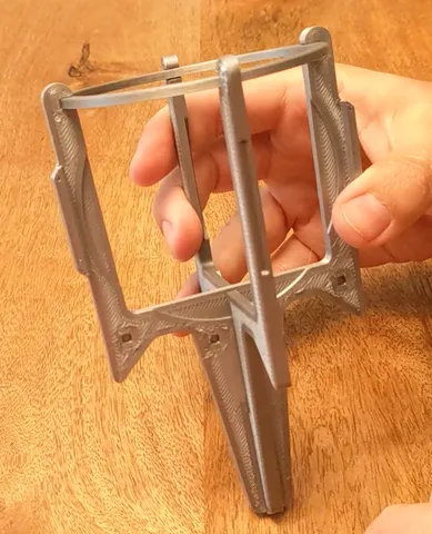
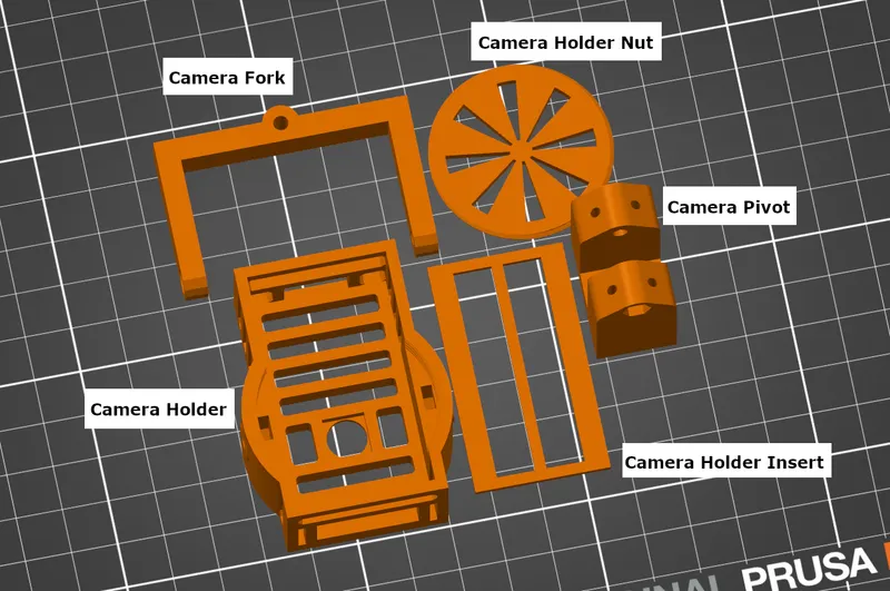
The parts to assemble are:
- Camera holder - the main body
- Camera holder insert - the flat rectangular part
- Camera holder nut - the thin, round wagon wheel. Note that this has threaded edges that mate with the threaded circular opening in the back of the camera holder.
- Camera fork - the forked part that goes around the camera holder
- Camera pivot - part that attaches to the center of the fork and mounts to the wall of the enclosure
- Camera Eyeshade (not pictured) - only needed for the wide angle parts, this snaps into the camera holder to lower the glare from the lights
Follow these steps to assemble the parts:
- Connect the fork and the camera holder
- Put two M3 nuts into the slots in the back of the of the camera holder. Use a small Allen key to push them all the way down.
- Align the holes in the sides of the fork with the holes in the sides of the camera holder.
- Insert an M3x8 screw in the left side of the fork and tighten it until it catch the nut.
- Repeat to install another M3x8 screw in the right side.
- Check the movement of the fork. If it is too hard to move, loosen the screws. If it will not stay where you position it, tighten the screws.
- Install the magnets into the back of the Camera pivot - they are a tight press fit.
- One way to do press the magnets is use a pair of channel locks or other large pliers. You can also use a vice:
- Put a stack of three magnets on the bottom jaw
- Line the magnets up with the hole in the pivot part
- Squeeze the top jaw to press them in - be sure you are pressing on the center of the other side of the camera pivot. If not, you may crush the screw or nut opening (if this happens, you can just open it up with a pair of pliers – it should not affect the function of the part)
- Repeat for each hole, putting three magnets into each. The magnets should be flush with the plastic or slightly proud when installed correctly.
- If you want to remove the magnets, a hole is provided in the back that you can use to force them back out. Be careful when doing so, and only use something with a blunt end to press them out.
- One way to do press the magnets is use a pair of channel locks or other large pliers. You can also use a vice:
- Alternate: If you want to mount the part using an M3 screw, press an M3 nut into the indentation between the two arms of the pivot part. This will allow you to put an M3 screw through an unused hole in the enclosure to attach the pivot to the wall or ceiling.
- Attach the pivot to the fork:
- Note that each arm of the pivot has a recess - one is round to accommodate a screw head, the other is hexagonal to accommodate an M3 nut.
- Thread an M3 nut onto the end of the M3x20 screw and use it as a tool to press the nut into all the way into the hexagonal recess on the pivot. Unscrew the M3 nut.
- Line the hole in the pivot up with with the hole in the center of the fork.
- Put the M3x20 screw into the side of the pivot, through the hole in the center of the fork, and thread it onto the nut you placed in step 2.
- Tighten the screw until snug.
- Check the movement of the fork and pivot. If it is too hard to move, loosen the screw. If it will not stay where you position it, tighten the screw.
- Install the glare shade (optional)
- If you are using the wide angle lens and you have lights in the enclosure, you may want to install the camera glare shade to reduce glare at the top of the image.
- Hook one arm into the vent hole on the side of the camera holder so that the bottom of the camera glare shade sits just above the camera opening.
- Hook the other arm into the vent hole on the other side.
- If the fit is too tight to get the second side into place, gently use a pair of pliers to stretch the vent hook into place. Take care that you do not break the arm off.
- Install the camera board in the camera holder
- Rotate the fork up so that the back of the camera holder is unobstructed.
- Inset the ESP32-WROVER board into the back of the camera holder at an angle, so that the WiFi antenna passes through the hole at one end. If it won't fit, you may need to turn the board around.
- If using a high angle lens, make sure the camera lens passes through the larger hole, then seats under the smaller round hole. This will hold the camera in place.
- When the board is fully seated, the camera should be visible from the hole in the front of the board.
- Place the rectangular insert into the back of the holder. The purpose of this plate is to protect the pins and keep them from getting bent when you install the nut in the next step.
- Carefully align the nut with the threaded circular opening. You can rotate it gently counterclockwise until it “clicks”, then rotate it gently clockwise.
- Only tighten the nut until it holds the board securely – over-tightening it may damage the board.
Software
The instructions and software needed to run the board can be found in the official PrusaCam repository. The official firmware supports the ESP32-Cam board, see the documentation for details.
Follow the instructions in the Rover README.md to set up a programming environment, install the required libraries and tools, and configure and load the PrusaCam software.
Once you've loaded the software on the board, configured the wifi credentials, and added your token from Prusa Connect, you should see the camera output in the Prusa Connect interface.
Install the camera in the enclosure
- Install the camera assembly on the enclosure.
- If you are using the magnet mount:
- Stick the magnetic base to the steel frame inside the enclosure.
- If you are using the screw mount:
- Choose an unused hole in the enclosure and insert an M8 screw from the outside of the enclosure.
- Line the center of the pivot up on the screw and thread the screw into the M8 nut until tight.
- If you are using the magnet mount:
- Ensure the positioning of the camera doesn't interfere with the motion of the printer, including the filament guide.
- Brace the ESP32-WROVER board from the top by holding the WIFI antenna and plug the USB-C cable into the power on the bottom of the board.
- Route the USB-C cable to the front or back cable hole in the bottom of the enclosure and out of the enclosure. If you intend to move the enclosure often, you may want to follow the official instructions for routing the cable under one of the feet.
- Connect the other end of the USB-C cable to the power adapter, and plug the adapter in. The board should now be powered up.
- Open the webpage for the the device (using the devices local IP address) or the Prusa Connect webpage. Use the camera view shown either place to adjust the camera's aim.
- If you use the device webpage, you can force a refresh, but if you do this too quickly, the webpage may become unresponsive.
Now you're done! Enjoy monitoring your prints from anywhere!
Tags
Model origin
The author marked this model as their own original creation.