Dumb Bot for AI Development

Description
PDFIntroduction:
This is the 'DumbBot', a 4 wheeled, Rear Wheel Differential Drive robot made for Artificial Intelligence (AI) applications. Inspired by the robots from the AI Tool Kit (AITK) this project seeks to implement a real-world version of these robots which students can use to create visual sensing AI robots. This project is meant to be cheap, easy to produce and available to computer science AI students who can now receive some formal engineering experience.
Physical Component Breakdown:
The physical robot is composed of two parts, a top and bottom section. The top section contains the electronics that read in ultrasonic sensor data and ports it to the Arduino UNO. The Uno has a Adafruit Motor Driver v2 which then can use the sensor data to actuate the rear wheel differential drives. The bottom section contains the two brushless DC electric motors.
CAD Files are available for both the top and bottom sections. The sections are split in two by a laser cut 3mm acrylic sheet. The 3mm acrylic sheet is where all electrical components are mounted.
Electronic Component Breakdown:
The electronics get slightly complicated. The electronics make use of 6 total inputs, which are ultrasonic sensors (RCWL-1601) Purchased from Adafruit or Mouser. The two output components are two DC Brushless Motors which are driven from a Adafruit Motor Shield v2.
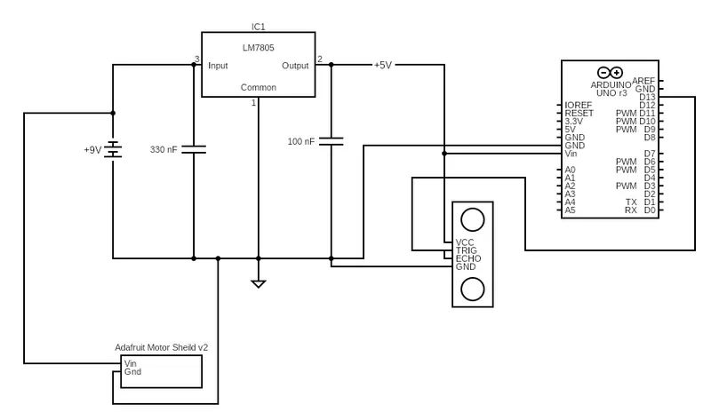
Since there's quite a few voltages that are required here where the Motor Sheild requires a 5-12V input, the Arduino Uno should run on a 5V and the Ultrasonic Sensors run on 5V. So, to solve this problem we can use a simple voltage circuit with input of a 9V or 2/3S LiPo battery. This voltage circuit allows us to patch the 9V/2S/3S LiPo directly into the Motor Sheild and after putting this through a simple LM7805 Voltage Regulator Circuit we can use the 5V regulated output to power the Ultrasonic Sensor and Arduino Uno.
Since this is slightly complicated, I have drawn a basic circuit diagram:
Pin Setup:
Pin Setup does vary depending on the boards chosen. I stuck with an Uno R3 but the main idea is the minimum requirements is six GPIO ports and the capability to drive two DC motors.
Concrete Evidence:
So, now that we have gone over some basic theory, let's look into some implementation. Using the CAD files provided you should be able to create a robot that looks something like:
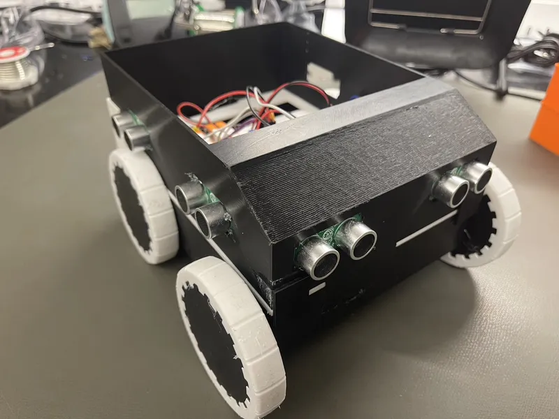
There's some extra key implementation hardware here. Let's inspect the wheels. The wheels are split into two main areas. The Rear Mounted wheels are attached directly to the DC motors to provide a differential drive for control. I chose rear wheel drive, but this is up to the individual to choose. The forward wheels are attached via a carbon fibre rod with ball bearings at both ends. More concretely I describe this in the next figure which shows the interior of the bottom section:
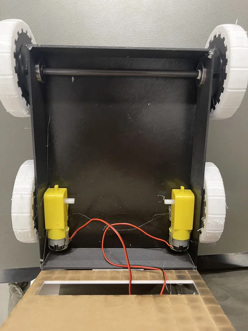
The above dictates exactly how to assemble the bottom component and it also shows the two DC motors that are the actuators of this project. Now that we have discussed the construction of the bottom, we can now begin to discuss the electronics. You can see a sneak peak of the bottom of the wiring is used to drive the motors. These wires are pulled upward and connected to the Arduino board.
The electronics are hard to explain but an annotated version is shown below:

To explain a bit about figure 4, it is basically a messier version of the electronics shown in figure 1. Important new components are the motor connectors which I chose to use inline wire connectors because it's easier to disconnect the base from the electronics. The right hand side ultrasonic sensors are connected as well. The interesting part about this setup is in the ultrasonic sensors. You can notice the ultrasonic Echo and Trig pins are wired together. This is an interesting new feature of the new ping Arduino library which allows the ultrasonic sensors to be driven by only a single digital pin. This is what allows us to drive so many ultrasonic sensors for this project.
Capabilities:
We've now discussed the general approach to the hardware of the Dumb Bot. The sample driver code included in this document shows how to read and actuate the motors. The capabilities of this are based to support Swarthmore College's Artificial Intelligence Lab 1 Course taught in Spring 2024. The lab goal was to solve a maze problem in the AITK using a robot with ultrasonic sensors on the right hand side and front of the robot. The method to solve this is using the right-hand rule which dictates that the easiest way to solve a maze is to just stick to the right-hand side of the maze.
The Dumb Bot mimics the potential of this robot where the robot can collect data from the front, left and right sides with auto straightening features. The auto-straightening feature is shown in the sample code which implements a proportional controller to make the robot automatically stick to a wall.
However, given these features we can now solve more complex problems such as environmental exploration and mobile sensing. You could notice that the robot is underpowered because it only uses a Uno R3, but it could be upgraded to work with OpenMV cameras and an Arduino Giga that would give it even more capabilities past just distance sensing from the ultrasonic sensors.
Thanks for reading, and I encourage anyone to try building this robot. It was a fun process and has a multitude of capabilities.
Tags
Model origin
The author marked this model as their own original creation.


