Bed Center Calibration Tutorial (using parametric crosshairs with rectangle)

Description
PDFParametric design (OpenSCAD) added!
This calibration tutorial is also described here! The model works with the Customizer panel of OpenSCAD, a free 3D CAD modelling software for creating solid 3D CAD models, which is very powerful for parametric designs. Creating your own rather than scaling one of the attached STL files is preferred as the design uses the nozzle extrusion width as a parameter of its design.
The tutorial is updated March 17, 2024 with a new parametric OpenSCAD model which can be used to fit your own heat bed/build plate (now also supporting the non-square build plates). The parameters of the model are self explanatory; define the build plate size through bed width and depth or use a rectangle ratio and the width. You can apply a modifier to reduce the size of the rectangle (when entering the actual bed size parameters, a factor of 0.9 will scale the rectangle to 90 % of the bed dimensions).
Please make your own center calibration STL by tuning it exactly to your printer setup:
// These parameters may be changed
// -------------------------------
// Define the physical build surface size, define the bed width
bedWidth = 200;
// Define the bed depth, or leave 0 to use rectangle_ratio
bedDepth = 0;

// Define width to depth ratio -> is unused, if "bedDepth" not 0 (so 1 is square)
rectangle_ratio = 1.0;

// Nozzle line width
nozzle_line_width = 0.4;

// Multiple of your z resolution including the first layer thickness
print_height = 0.2; // This can always be scaled in your slicer!

// Parametric rectangle and crosshair modifier (make the calibration print smaller to fit the bed if the center is off)
printModifier = 0.9; // default = 0.9 i.e. 10 % smaller
--------------------------------------------------------------------------------------------------------------
What! Not in the center?
I noticed that with large prints part of my skirt or brims sometimes was printed outside the heat bed print area. Apparently, the printer does not have the correct heat bed center in the firmware.
This thing helps you to find the center of the bed and aids in changing the bed center to the actual bed center. Instructions are provided below for you to change your center.
Supported firmware
Note that this works for e.g. Marlin based firmware, e.g. Skynet3D! More firmware types are supported, see this page.
Note for unsupported firmware
For stock Anet boards (or if you cannot or do not want to mess with gcode) you can make this also work by printing spacers or custom end stop mounts.
Walk-through
Printer center seems to have an off-set?
With the stock firmware (a customized older version of Repetier) I have not tried to find a solution for my problem, but recently I updated my printer with an auto bed leveling sensor which requires an update of the printer firmware (to Marlin firmware). I updated to the latest Skynet firmware (v2.3.2 fix 2). Please note that Skynet3D printing software is obsolete! All changes for the Anet A8 have been implemented in the Marlin sources.
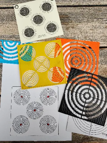
After the firmware update I noticed that the prints are printed off-set of the heated bed center (again). This can easily be checked by printing the thing I uploaded here. The cross should be exactly in the center of the heated bed; the distance from the outer squares to the edge of the heated bed should be similar/equidistant.
Fix the off-set!
In my case the bed is off center by 2 mm in both X and Y direction (ignoring the signs here). There are a few solutions to solve this (see Marlin bed dimensions at reprap.org). As I closed up my main board after the firmware flashing (using a private remix (now publicly available here: 0scar's modular Anet A8 electronics casing) from c_wolsey's Anet A8 Electronics Case; I increased the height of the casing so it can hold a Raspberry Pi, the main board, a 4-channel relay module, an opto-coupler for the auto level sensor and a heatbed Mosfet), I had no quick access (maybe combined with a little laziness and lack of time) to change the firmware configuration file and upload a new version, so I decided to go for the second method: changing the off-set through g-code command and store the new off-set to the printer memory. In my case the center of the bed required an offset of -2 mm for the X direction (just measure in the X direction the distance from the outer squares to the edge of the heated bed and subtract the 2 values and divide them by 2; in my case this led to (8-12)/2 = -2 mm). A similar action needs to be done for the Y-direction; this resulted in 2 mm off-set.
Use a terminal to access the printer to directly send command to the printer (this can be e.g. done in Cura or Pronterface). I used the terminal available in the OctoPrint interface.
Send the code: M206 X-2 Y2. The values specified are added to the endstop position when the axes are referenced, so this tells the printer that the center of the printer is located at the given values with respect to the stored values in the configuration file. To store the new center send code M500.
The first photo shows the before center calibration, the second photo after calibration.
Now your printer has a new center!
Category: 3D Printing Tests and Calibration
Tags
Model origin
The author marked this model as their own original creation. Imported from Thingiverse.