Blobifier for Voron 2.4 350mm Printer

Model files
Tray.stl
Base_Miller350.stl
SB_Shaker.stl
Servo_Arm.stl
Bucket-Miller350.stl
SB_Shaker_arm_poo.stl
SB_Shaker_arm.stl
Brush Holder.stl
Bucket-Brush.stl
Blobifier Miller 350 v48.f3d

Other files
Shaker.zip
Model origin
The author remixed this model.

Differences of the remix compared to the original
Overview
This modification of Dendrowen's Blobifier for Voron 2.4R2 modification builds on the original by:
- Replacing Bucket Sensing Switch with PCB mounted Hall Effect Transistor,
- Combining the Mount and Base into one part in order to create space for PCB mounted JST-XH connector,
- Incorporating existing Purge Bucket and integrated Brush in place of the one provided in the original Bolbifier design.
This version is designed to work with Happy Hare control software, ERCF V2, and Filametrix. Purge Buckets are designed for the Voron 2.4R2 350x350mm build volume version. All other parts should work on the other Voron 2.4R2 variants. Fusion 360 Model is included to simplify any local modifications that may be required. The files provided herein should be all that is needed for the Blobifier modification. ERCF V2 and Filametrix can be downloaded from their respective GIT hub sites.
Objectives
The primary object in this modification was to improve JST-XH connector mount reliability and overall wire management. A secondary goal was to add Bucket Home location to the already installed sensing. Finally, this modification incorporates the already existing purge bucket and brush from previous modifications.
Switch Replacement
The existing D2F-5L switch required a large area in lower portion of the Base. This switch sensed only the presence of the Bucket and not its fore/aft position. If the Shaker assembly is not positioned against the Base, the Toolhead could strike the Shaker flange and potentially break something and/or cause X/Y stepper shifts. This is particularly true if Filametrix filament cutter were mounted just forward of the Shaker assembly and “restore_xy_pos” was configured.
To provide both Bucket Installed and Fore/Aft position sensing, a small diameter magnet was installed in the side of the Bucket 7mm aft of the Shaker Arm and the D2F-01L switch was replaced with a Hall Effect A3144 transistor. This transistor outputs a ground seeking digital signal. This allows it to be connected to any digital input port including 3.3Vdc ones. The transistor output can therefore be connected to the same pin that the D2F-01L switch used. The signal is inverted necessitating the Klipper Pin definition to be prefaced with “^!” ("^" signifies a pull up resistor).
The combination of the small magnet and the Hall Effect transistor provides an Installed signal only when the Bucket is properly positioned next to the Base and the Shaker Arm is within 3mm of the Base.
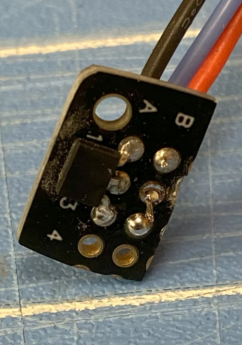
The Hall Effect Transistor was installed on a small breadboard PCB cut from a larger commercially available PCB. See BOM. This allows the wiring to be soldered to the PCB rather than the legs of the transistor. Proper transistor location is insured when the PCB is inserted into slots in the modified Base. See installation procedure.
Bucket Sizing
The length of the Blobifier Bucket is the same as the original design. The width was increased to a dimension equal to the distance between the Base and the opposing bed extrusion less 1mm. This forces the Bucket to be next to the base when properly installed. This results in a much larger Bucket compared to the original. Capacity has been demonstrated to be greater than 400 Blobs if shaken every 20 filament changes.
JST-XH Mount
The 4 position JST-XH connector was mounted on a small PCB which was in turn inserted into slots provided in the modified Base. The advantages of mounting the JST-XH connector are:
- Connector is designed to be PCB mounted not direct wired to pin connection,
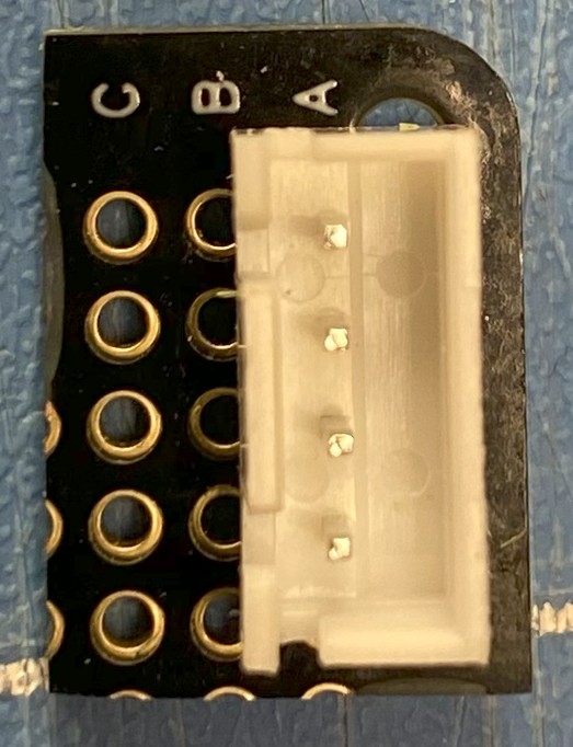
- Soldering wires directly to the pins on the connector can distort the pin geometry, making mating connector insertion difficult,
- Pins not firmly soldered onto a PCB are subject to being pushed out of the connector body when a mating connector is attempted to be inserted.
- PCB mount provides robust connector retainage throughout many insertion cycles. Mounting position is no longer reliant on small flange printed in the Base,
- The JST-XH PCB has several interconnected plated through holes allowing both the Servo and A3144 wires to be soldered to unique dedicated holes rather than direct solder to connector pins.
Other Modifications
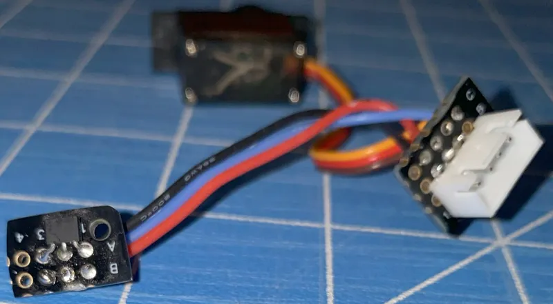
The Base was hollowed out to provide space for wire routing/storage.
This was possible by incorporating the mount into the base. Hollowing out the base allows the Servo, A3144 Transistor PCB, and the JST-XH PCB to be prewired prior to mounting in the Base. This simplifies the soldering and provides for easy installation.
An existing Brush and Waist Bucket was retained from previous modifications. The Brush Bucket was modified to fit flush with the back, center of the print bed. This captures the small amount of filament that is brushed off during nozzle cleaning. It also allows filament fragments that fall on the bed to be brushed directly into the Brush Bucket. Three (3) large magnets are press fit into each of the Brush Holder and the Brush Bucket to ensure that the Bucket is firmly held in place between cleanings. The STL files are included for these items.
BOW
| QTY | P/N | Description | Source |
| 1 | JST-XH | Connector | https://www.amazon.com/gp/product/B0B2R99X99 |
| 1 | A3144 | Hall Effect Transistor | https://www.amazon.com/gp/product/B09PG3PGH6 |
| 2 | M3x8 | SHCS Screws | https://www.amazon.com/Socket-Screws-Bolts-Thread-100pcs/dp/B07CMRQ3TB |
| 4 | M3x8 | FHSC Screws | https://www.amazon.com/DYWISHKEY-Stainless-Countersunk-Assortment-Wrenches/dp/B08QD86364 |
| 2 | M3 | T Nuts | https://www.amazon.com/Hulless-Sliding-Fastener-Aluminum-Accessories/dp/B08NZMD2BJ |
| 1 | 3x2mm | Magnet | https://www.amazon.com/gp/product/B09SLFSRBP |
| 1 | MG-90S | Servo | https://www.amazon.com/dp/B07L6FZVT1 |
| 3 | M2x6 | SHCS Screws | https://www.amazon.com/gp/product/B07FLLGW19 |
| 1 | M2x6 | FHCS Screw | https://www.amazon.com/DYWISHKEY-Stainless-Countersunk-Assortment-Wrenches/dp/B08QD86364 |
| 1 | Brush | Brass | https://www.amazon.com/gp/product/B091J3T11Q |
| 4 | M3 | Heatsets | https://www.amazon.com/gp/product/B09MCWTBCC |
| 1 | PCB | https://www.amazon.com/dp/B09WZXHMDG | |
| 6 | 10x2 | Magnets | https://www.amazon.com/gp/product/B092MB697H |