The Webbinator
Description
PDFBackstory: I saw a model of a similar mirror here on Printables and figured, let's make it more interesting by adding some LEDs. So, this is inspired by, but not based on James Webb Decoration.
Warning: This thing takes a lot of time to print (18 tiles by 3 hours each, and then some more), and even more time to put together and solder the LED strips. For adventurous makers only.
There is a custom version of WLED for this installation with some special 2D effects, see this branch on GitHub: https://github.com/apanteleev/WLED/tree/webb
What you'll need:
- Hexagonal mirrors - 18 count. The models are designed for this specific set, and you'll need two sets. They might not fit exactly after everything is assembled, and I used a guillotine paper cutter to trim them where necessary.
- Structural filament for the tiles. Any color will do, it's not visible from the outside. I used ASA for longevity and temperature stability; PETG didn't work well as the tiles were too detailed. PLA might be OK if you don't plan on overheating it or taking it to a certain desert festival.
- Translucent filament for the shields (the parts that cover the LED strips). Clear PETG worked well.
- White filament for the board mounting plate, as it doubles as a reflector for the backlit cover.
- A multi-material printer, with black PLA and other translucent PLA colors (clear, blue, red for the NASA logo) to print the center cover.
- About 7 meters of 144 LED/m addressable LED strips. I used WS2815, but other 12V LEDs should work too.
- About 1/2 meter of 144 LED/m 12V white LED strip for the center cover backlight.
- ESP32 dev board
- A pair of 5V relays (both used in parallel to support over 10A current)
- MOSFET for driving the center backlight
- DC-DC converter capable of producing 5V 1A or so
- INMP441 microphone module (optional, if you want audio reactive effects)
- SN74AHCT125N level shifter (acts as a protector for the ESP too, I burned 2 ESPs here…)
- PCB push buttons, through-hole mounted, 8mm long or so - 2 count (optional, if you want buttons on the front side)
- Some screw terminals
- 12V 15+A power supply (I used a slim power supply from Aliexpress but it's not great and it's external to the mirror anyway)
- Many screws and nuts:
- M4x20 hex socket screws for putting together the frame - 76 count
- M4x25-30 hex socket screws where the frame has attachments - 8 count
- M4 nuts - 84 count
- M4x6-8 screws for attaching the board mounting plate - 4 count
- M3x4 screws for mounting PCBs - 8 count
- M2x4 screws for mounting the MOSFET - 2 count
- M3x8 screws for securing the front cover - 5 count
- A flexible screwdriver is best to reach tight places, like the iFixit one with the extension
- Lots of thin wires
- A few meters of thick wire to route the power web
- An 8-wire ribbon cable with pin header socket connector, and the angled connector (for the front panel with buttons and microphone, optional)
Also note: I'm not an experienced PCB designer, so the KiCad projects included here probably suck. And their trace widths etc. are optimized for 1-layer PCB manufacturing using CNC isolation routing; if you order the PCB somewhere, better redesign it as a proper 2-layer thing.
Build process:
- Print the tiles (19 total). Default settings should be fine.
- 1x Tile_Center
- 6x Tile_Inside
- 6x Tile_Outside_2_sides
- 5x Tile_Outside_3_sides
- 1x Tile_Outside_3_sides_WireHole (this one goes at the bottom)
- Assemble the frame using the tiles. The layout should be obvious from the pictures. Each pair of tiles is connected with 2x M4x20 screws and nuts. Skip all outermost screws for now, you'll need to flex these seams apart a little bit to install the shields later.
- Print the shields with clear transparent PETG. Use default walls and infill (15% gyroid looks OK).
- 42x Shield_Top (enable ironing on the top surface, looks good)
- 5x Shield_Side_NoTrim
- 1x Shield_Side_NoTrim_WireHole (matches the WireHole tile)
- 12x Shield_Side_LeftTrim
- 12x Shield_Side_RightTrim
- Do a test fit with some of the shields and the frame. The shields should insert into respective holes snugly but without excessive force. Top shields go between the tiles and may need some sanding on the short sides to make the seams invisible. Side shields go on the sides: NoTrim version matches the locations where both sides bend “down”; LeftTrim or RightTrim versions match the locations where the respective side bends “up”.
- Install the power rail wires by weaving them through the hexagonal holes in the frame (see the back side photo). I used 14AWG solid copper stripped wire; 16AWG should be OK too. Use at least two rails, the inside one is the ground, and the outside one is +12V (connected to power supply through a relay to save power when the device is off). I have 4 rails to make connecting the outside LEDs easier (G/+12/G/+12).
- Cut, glue, and solder all the addressable LED strips. This is by far the longest part of the build.
- All the “top” strips that go between the tiles are one segment, 546 LEDs; all the side strips are another segment, 402 LEDs. There is no data connection between the two.
- Connect the power to the strips frequently by tapping into the circular power rails.
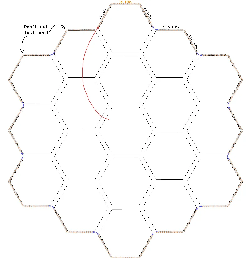
- Top strips are 13 LEDs each, as shown below:
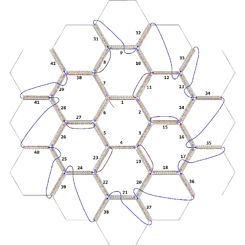
- Side strips that cover the 3-side tiles are 40 LEDs each (13+14+13), and ones that cover the 2-side tiles are 27 LEDs each (13+13 and one in the middle). Just go clockwise from the top:
- It's a good idea to test the LEDs at this point (or earlier, as you go through the soldering process) by connecting them to the ESP32 running WLED.
- Use WLED with Audio Reactive usermod if you're adding the microphone.
- Install all the Shields.
- Make the PCB with the buttons and the microphone (the HexMirrorButtons project), solder the ribbon cable to it.
- Print the CoverAdapter (black) and BoardMountingPlate (white).
- Install the CoverAdapter over the center tile, covering parts of the top shields. Orient it so that the side with 3 holes faces down.
- You'll need to remove 6 of the 12 screws connecting the center tile to the other tiles, and replace them with longer screws to mount the cover adapter.
- Attach the buttons/mic PCB to the bottom side of the CoverAdapter so that the buttons occupy the 2 outside holes and the mic is facing the middle hole. Use M3x4 screws.
- Attach the BoardMountingPlate to the CoverAdapter from behind, so that the flat part of it faces forward, and the ribbon cable from the PCB goes to the back of the mounting plate. Use M4x4-8 screws to secure the plate to the adapter.
- Cut and glue the white LED strip to the walls of the CoverAdapter front well, so that the LEDs are facing inside and illuminating the mounting plate - it acts as a reflector.
- Make the PCB with the ESP32 (see the note above about the KiCad projects… basically, better make them from scratch, just fit the mounting holes)
- Mount all 3 boards on the plate, connect them with wires.
- Add a power connector somewhere in the bottom tile.
- Note that the ground can be directly connected to the circular power rail; the +12V wire should go into the relays and into the PCB power input connector.
- Print and mount the center cover.
- The included STL does not have any image on it. I used Bambu Slicer to insert a NASA logo SVG and assign colors to its parts. You can use any image you want as long as your printer can support all the necessary colors at once.
- For best results, use a smooth plate, 100% infill, and maybe a 0.2-0.25 mm nozzle. The print takes forever, but then the logo looks great from a few feet away.
- Insert the cover into the adapter, use 5x M3x8 screws from the sides to secure it.
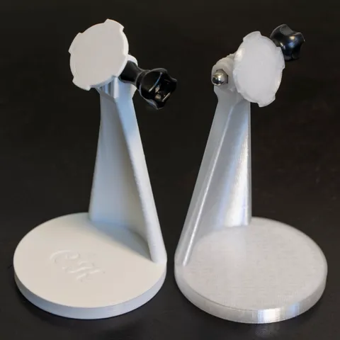
- Add the mounting brackets.
- Print MountingBracket and MountingBracket_Nut
- Attach the brackets to the horizontal connection between tiles, 2nd from the top, in the far apart positions.
- Glue the mirrors to the frame.
- I used thin double-sided adhesive tape, so that the mirrors can be removed if necessary (not super glue). The result is not perfect, as the mirrors warp a little bit.
- Hang it on the wall.
- Enjoy!
Possible modifications:
- You can skip all the RGB LEDs and just use opaque shields. This makes the project much easier but also not as cool.
- You can remove the microphone and/or the buttons. If both are removed, the supplementary PCB is not necessary - just change the CoverAdapter model to remove the holes.
- Using a display instead of a backlit plastic cover in the center is an interesting idea but it would require some programming and maybe a different controller.
Model origin
The author marked this model as their own original creation.