Qidi X-CF Pro Hot End Upgrade


Description
PDFWhy
Qidi provides two hotend assemblies with the X-CF Pro, one for high temperature and one for low temperature. Swapping between them was a hassle to remove 9 M3 screws, loosen 4 other M2 screws, and gave me anxiety each time I cycled the ribbon cable connector since they are a pain to replace and the connectors are fragile. This modification eliminates the need to swap extruder assemblies. If you prefer cheaper nozzles, like me, then just remember to change the nozzle between abrasive filaments and standard materials. If you buy an expensive diamond tip nozzle then no more replacing nozzles either.
You can print with PLA/TPU/PET/ABS/Nylon/PAHT-CF/PET-CF/ABS-GF25 etc. all from this single setup.
Orbiter V2 - $45 USD
Rapido K500 HF - $75 USD, Select the option HF
4020 Axial Fan 24V - $13 USD
3010 Blower Fan 24V - $5 USD
M2.5 to M3.0 Standoff QTY 2 - $7 USD each
JST-XH Crimping Set - $7 USD, Select the option IWS-2820 2.54 XH-F
Brass Inserts Set - $13 USD, select the option M2.5 & M3
5 mm Aluminum Rod, short length - $2 USD
M3 Tap - $8 USD
M3 Screw Hardware - $13 USD
Nozzles - $10 USD, common V6 style widely available, Qidi style incompatible
Tools Used
- 3D Printer: Print all shims & spacers in PA12 or equivalent high temperature resistant and stiff material.
- Soldering Iron: Install QTY 3 heat inserts where instructed.
- 3 Axis Mill: The structural bits remain aluminum. If you cannot machine it yourself then order through SendCutSend/JLCPCB/PCBWAY/Fathom. That is why I added the final two images, any machinist house can quote you with those images and the STP files. I wouldn't expect it to be more than ~$30 USD, and then you can save money by not buying the taps. Or enlarge the holes and print in Nylon/PC.
- Dremel: Cutting and trimming various parts
- Taps: M2.5 & M3
- Wire Crimps
Step 1
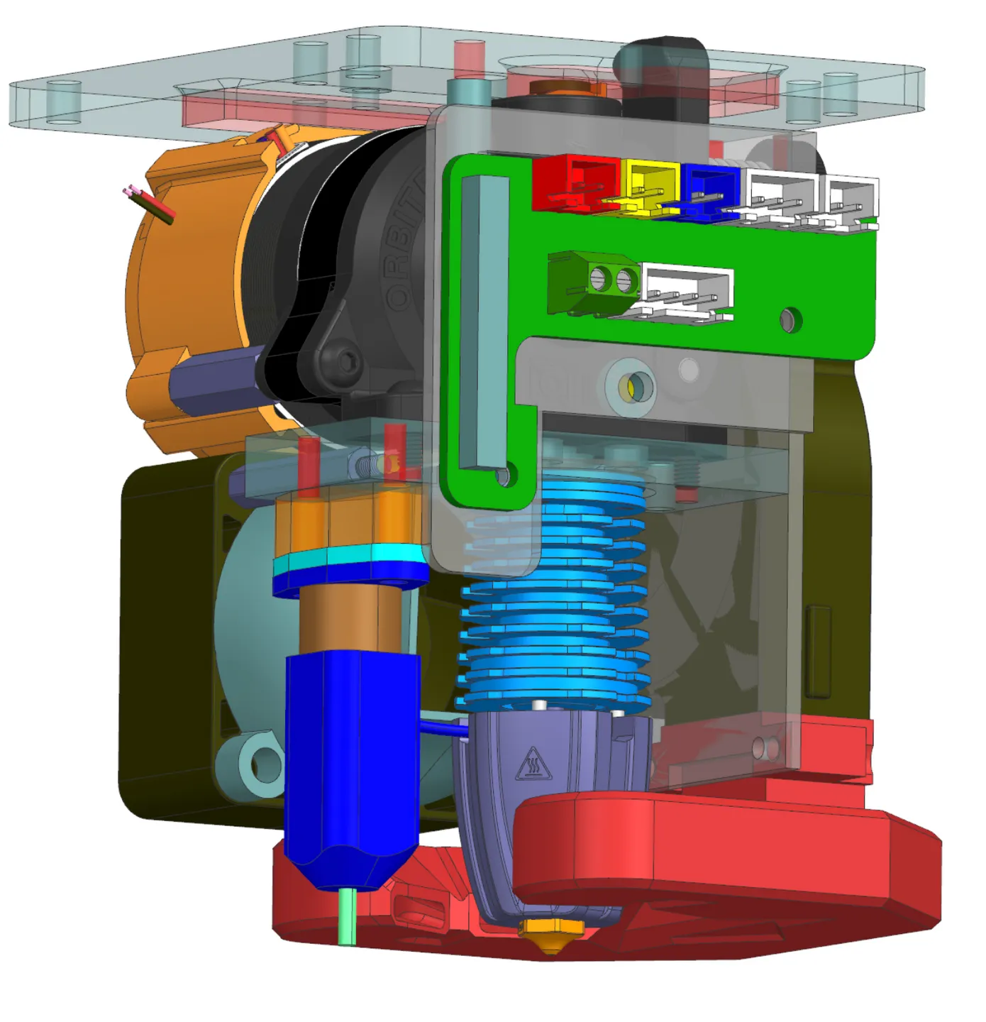
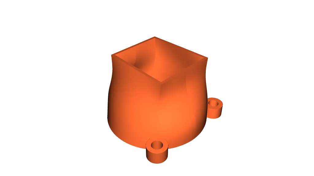
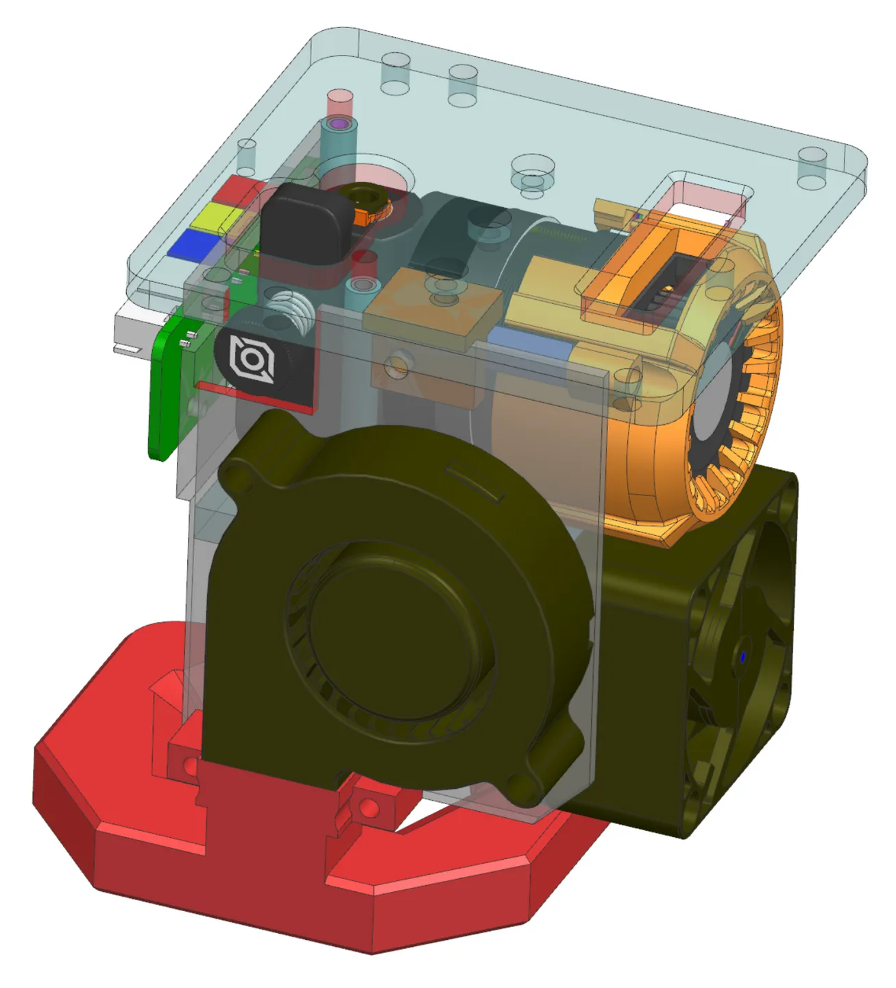
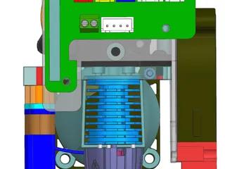
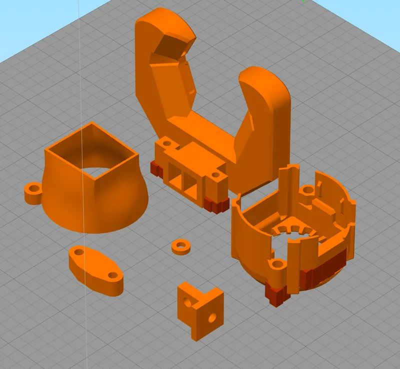
Print the spacer, shim, BL_Touch_shim, duct, plenum, and shroud in the orientations shown below. I used PAHT with 0.2 mm layer heights. The shroud needs supports at the two screw hole features and the ventilation hole. The plenum needs supports at the two hole features only. It is important to NOT add supports anywhere else or it will block the air flow.
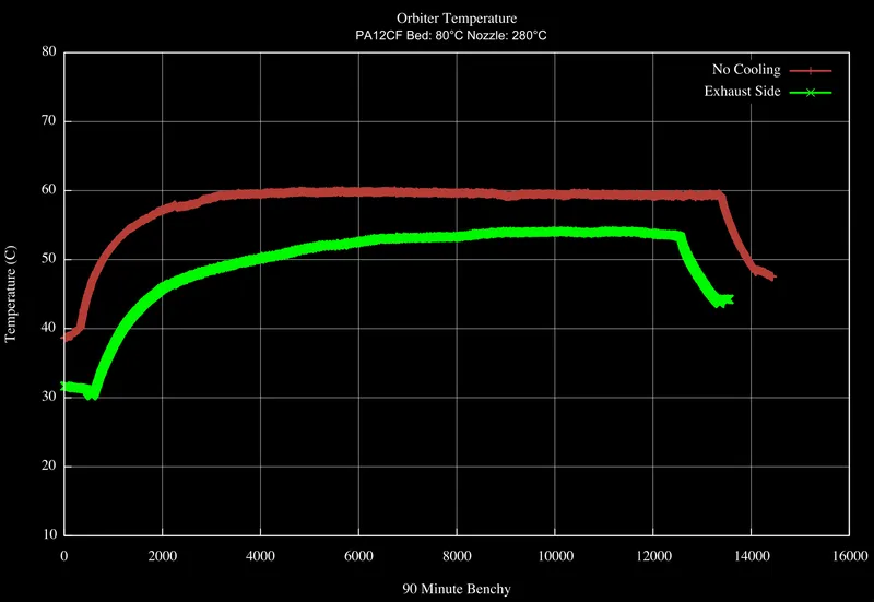
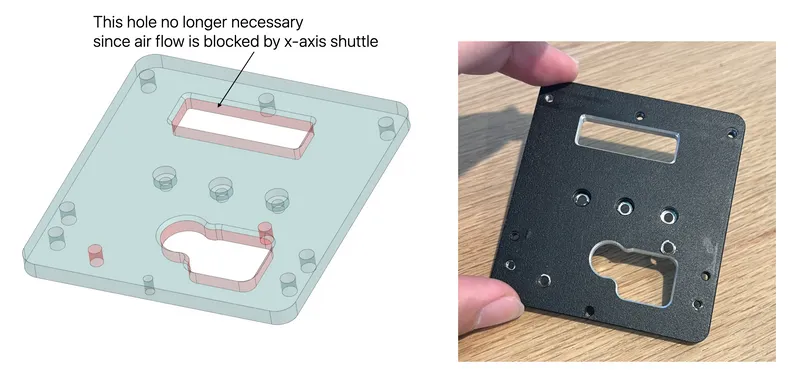
*Edit 3/23/2024 - the shroud exhaust ventilating towards the top was providing no benefit since the X-axis shuttle was blocking the air flow. I've rotated the fan inside the shroud so it can exhaust to the side facing the ribbon cable instead. If you want to actively cool the Orbiter V2 to keep it below 80°C then I recommend this version ‘shroud-side-exhaust.stl’. It isn't really necessary in my mild climate at my typical volumetric flow rates but I haven't printed anything in hot summer months yet either. I guess the cut in the aluminum is just weight savings now that air will not blow through the rectangular hole.
Step 2
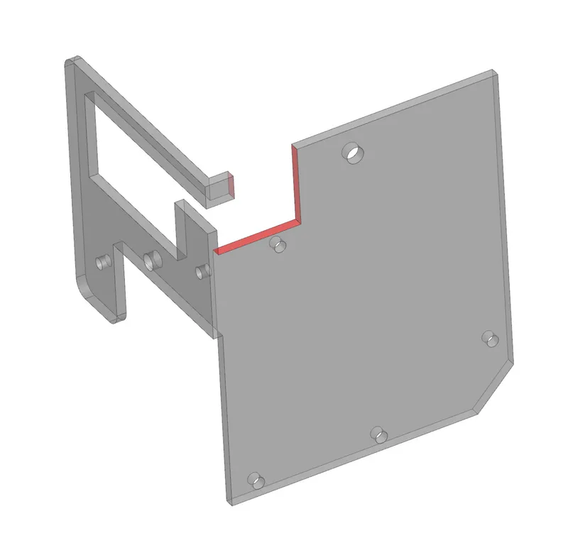
Machine away the aluminum faces highlighted in red color from the original mounting bracket. This will create space for the Orbiter V2 and ventilation for keeping the extruder cool when the chamber gets hot. The two holes are needed to mount the Orbiter V2 to the block. This could be easily printed but seeing as how it is the main brace that supports ~300 g mass of everything below it and given that temperatures in the enclosed chamber reach 60°C, it was just as easy for me to machine it and retain the benefits of aluminum.
Step 3
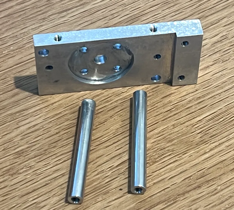
Machine the block. The most difficult part in the whole process. All identical dimensions to the original part but one wall is extended to make space for one of the Orbiter V2 mounting screws. And two M2.5 tapped threads for moving the fan to the rear of the extruder. The M2.5 tap is uncommon and needed in two places. Or outsource the whole part for ~$30 USD to SendCutSend or JLCPCB or some such other fabricator.
Step 4
Order 5 mm aluminum rod & M3.0 taps. Cut two pieces to 39.25 mm and tap each end, these are for mounting Orbiter V2 to the block. Cut two more pieces to 18 mm and tap each end, these are for mounting the shroud to the Orbiter V2. Or, outsource these too for ~$15.
Step 5
Cut a small pocket in the aluminum frame with a Dremel so the Orbiter V2 adjustment screw can have clearance.
Step 6
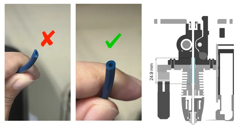
Cut a Bowden tube with 4mm OD and 2 mm ID to a length of 24.9 mm. This will be inserted inside the hotend and extruder. Use a blade to make a clean cut. Do not use scissors or deform the tube by crushing it.
Step 7
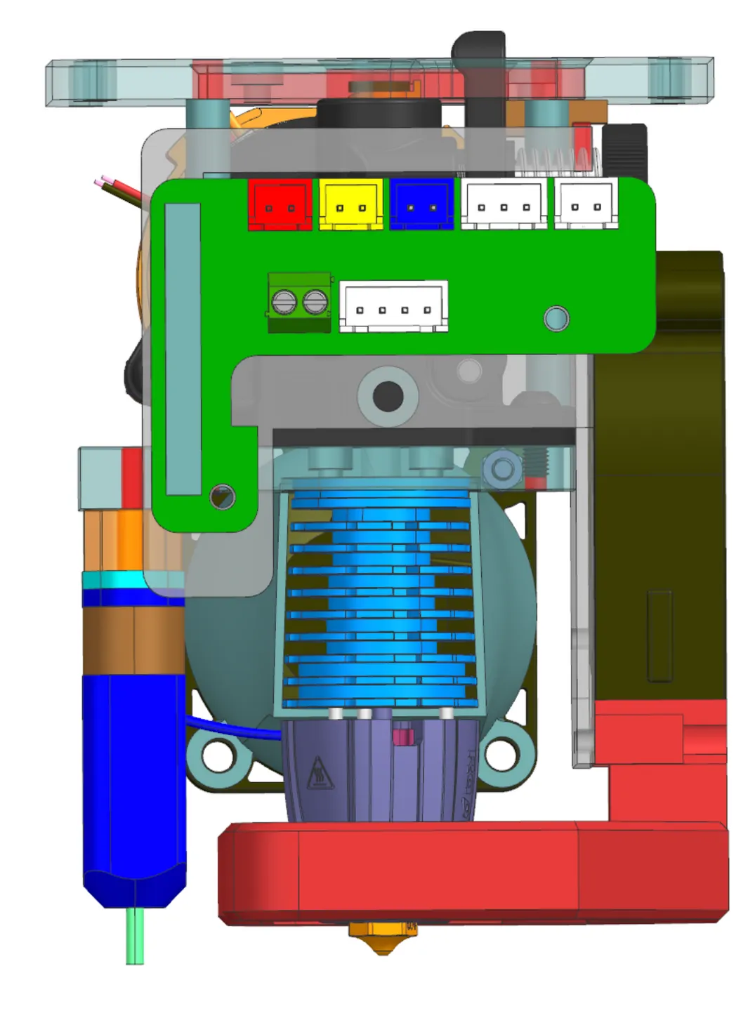
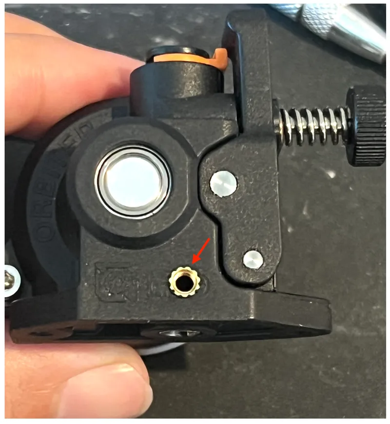
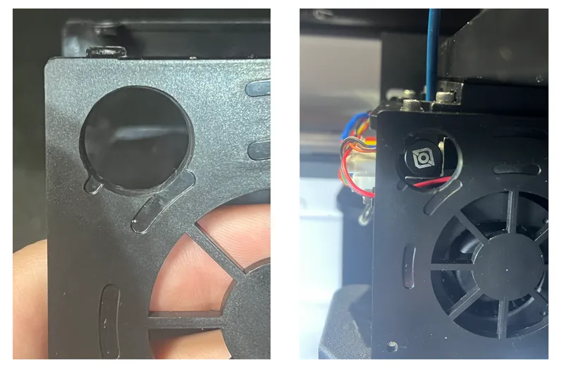
Drill a 4 mm hole into the front of the Orbiter V2 so that you can heat press a brass M3x3 nut into it. The position of this is important because the frame will attach to it and ultimately determine where the part cooling plenum lands relative to the nozzle. Start with a small 2mm hole and increase it by 0.5mm until reaching 4mm diameter. Be delicate. You don't get a second chance with this. I use this drill bit set. Do a few fit checks with the other parts and mark your hole with a center punch or marker. I aimed for the center between the ‘D’ and ‘O’ of the text from LDO label. But ended up a bit to the left as seen below. Clean out any shavings so they don't jam up the gears of the extruder.
Step 8
Enlarge the hole to 4 mm diameter on the frame, really just strip away the threads on the nut Qidi welded to the inside. If the nut falls off don't worry, you've printed a spare already.
Step 9
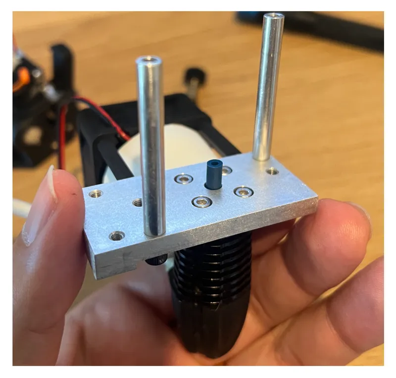
Install two M3x3 brass heat set inserts as shown to the shim.
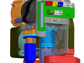
Mechanical Assembly
A. Mount Rapido K500 HF to the block bottom side with the provided M2.5x4 screws from the kit. Install 24.9 mm tube inside the throat.
B. Mount Orbiter V2 to the block topside. Visually confirm there is no gap which would indicate your Bowden tube is too long. Tighten the two M3x8 screws provided with the Orbiter V2 kit. You may need to remove the thumb screw of the Orbiter V2 for screw driver access.
C. Press the 3010 Axial Fan inside the shroud past its retention clips. Mount the fan and shroud to the rear of the Orbiter V2 using the 18 mm length aluminum rod and two M3x10 screws.
D. Install the M2.5 to M3.0 Stand Off into the block. Mount the 4020 axial fan to the standoff with QTY 2 M3x20 screws. The sticker on the 4020 axial fan faces the direction you want the air to flow so make sure it points at the Rapido K500. Mount the duct to the 4020 axial fan with QTY 2 M3x25 screws plus two nuts.
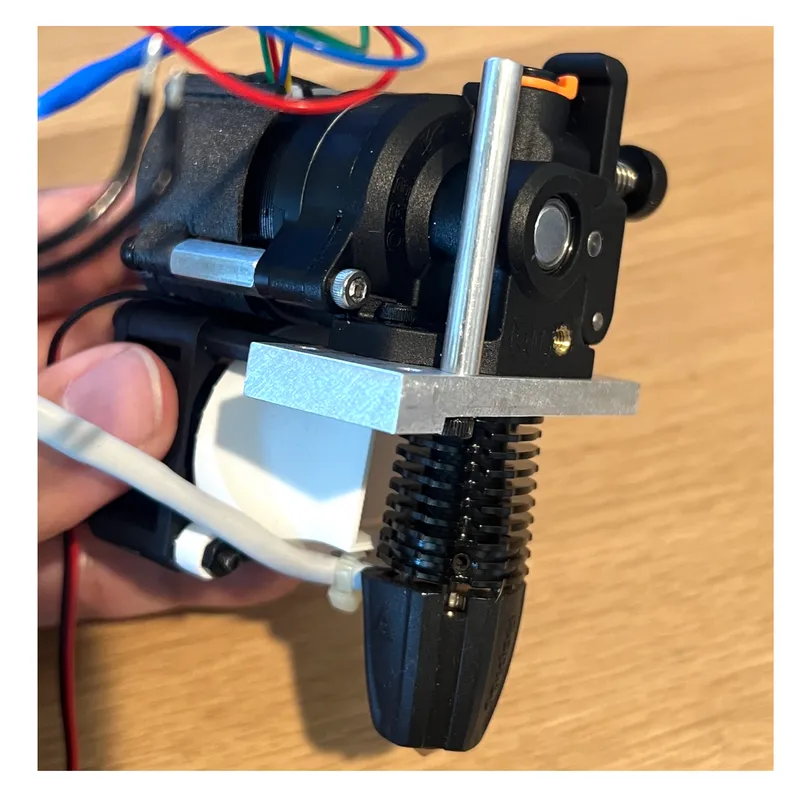
E. Mount the original mounting bracket to the extruder assembly using the 39.25 mm tapped rods and QTY 2 M3x8 screws. Their length matches the height of the Orbiter V2. The mounting bracket will rest on these three surfaces.
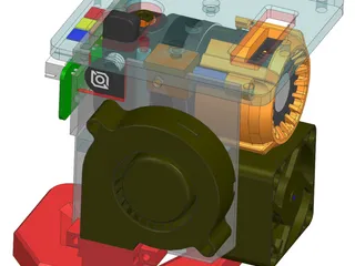
F. Install the shim onto the inside of the frame as shown.
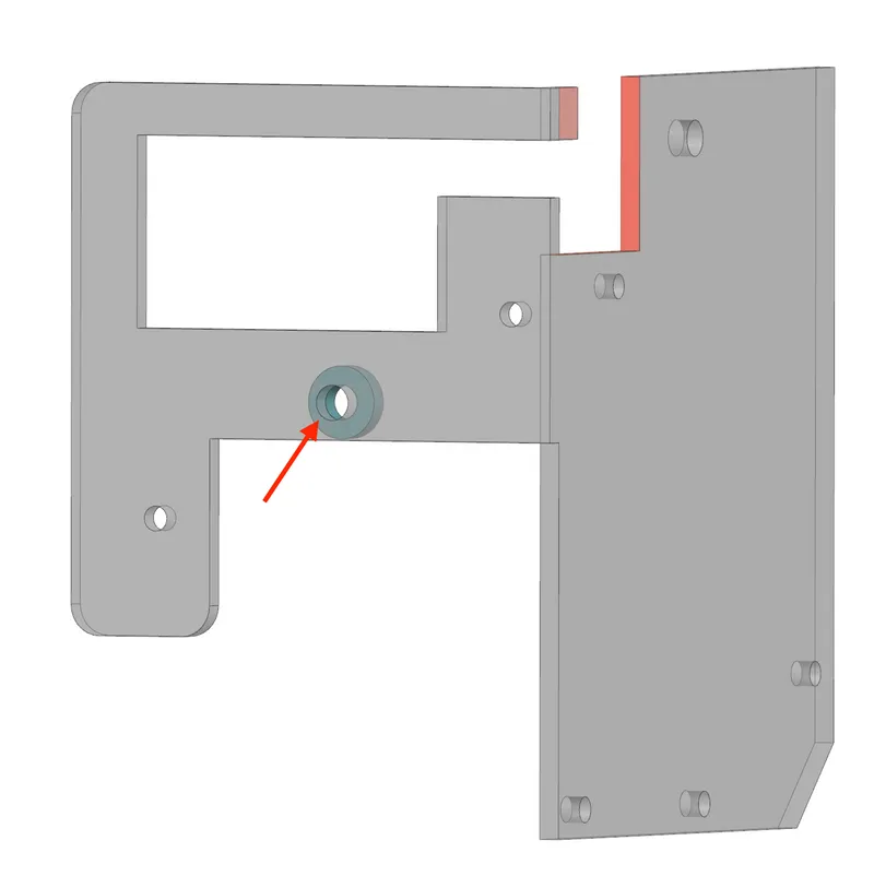
G. Place the 2 mm height spacer over the brass nut installed into the Orbiter V2. Install the frame with a single M3x6 screw to the front of the Orbiter V2. Do NOT torque down the screw too tightly. Finger tight fit is fine. You do not want to pull the brass nut out of the Orbiter V2 Housing or crack the housing. The frame is still free to rotate. Install a M3x6 screw to the top of the bracket (reusing one of the recessed screw holes) so that the shim+frame are tied to the mounting bracket. Now the frame cannot rotate. If the frame is not square with the rest of the assembly or the final screw does not install then the hole you drilled into the Orbiter is not identical to mine. No worries, drill bits wobble sometimes. Just modify the shim STP file until it fits and squares up the frame to the rest of the assembly firmly.
H. Install the plenum for part cooling with QTY 2 M3x16 screws. 5015 fans are not standardized in their detailed dimensions so you may need to modify the geometry to get a good fit. Feel free to modify the STP file included. 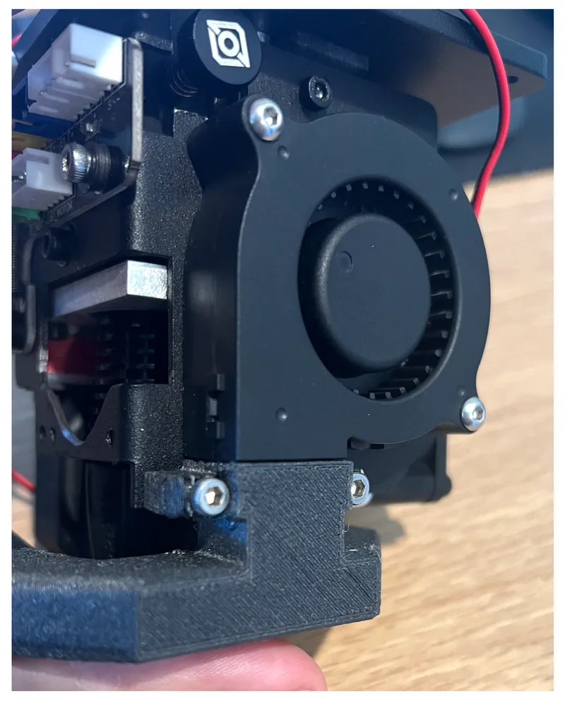
I. Install the BL_Touch_shim with its assembly with QTY 2 M3x16 screws.
Electrical Assembly
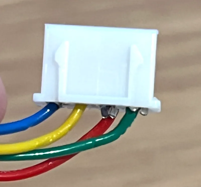
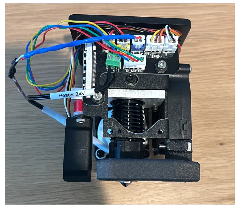
J. Trim the 4 extruder wires to a length of ~100 mm. Crimp the terminals to the copper and install into the JST-XH connector as shown.
K. Cut off the connector that came pre-installed on the Heater 24V wire. Install two wires into the green terminal on PCB. Polarity is not important.
L. Cut off the connector that came pre-installed on the Thermocouple wire. Extend wires if necessary*. I wanted to add ~80 mm so my photo shows heat shrink tubing covering my solder joints. The extra wire length was included with the kit. Crimp terminals to copper and install to the JST-XH connector. Polarity is important but can be easily reversed if the temperature reading is wrong during device start up. I carefully pulled back and trimmed the braided heat-resistant fraying insulation to see which wire has red color insulation to make sure that one goes to the ‘+’ side on the PCB connector and was wrong. The screen read “0” when I tried to preheat the nozzle and load my filament but the nozzle was certainly hot. I had to reverse my wires as you will see in the final mounted photo. For me, red went to the PCB position labeled ‘-’ for connector ‘E1_T’.
- You can avoid soldering by simply rotating the Rapido K500 90° so that its wires route towards the front instead of towards the rear. I chose to point my wires towards the rear for visibility purposes of the camera I have installed in my enclosure. I have perfect line of sight between my part cooling fan and BL Touch so my camera can directly see the nozzle tip as it extrudes filament. I did not want the thermocouple and heater wires occluding that view.
M. The 4020 axial fan and 3010 blower fan will now be connected in parallel so they both run at the same time. Solder red to red and black to black. Shield with heat shrink tubing. Crimp terminals to copper and install to the JST-XH connector. Install to the ‘MB_F’ connector.
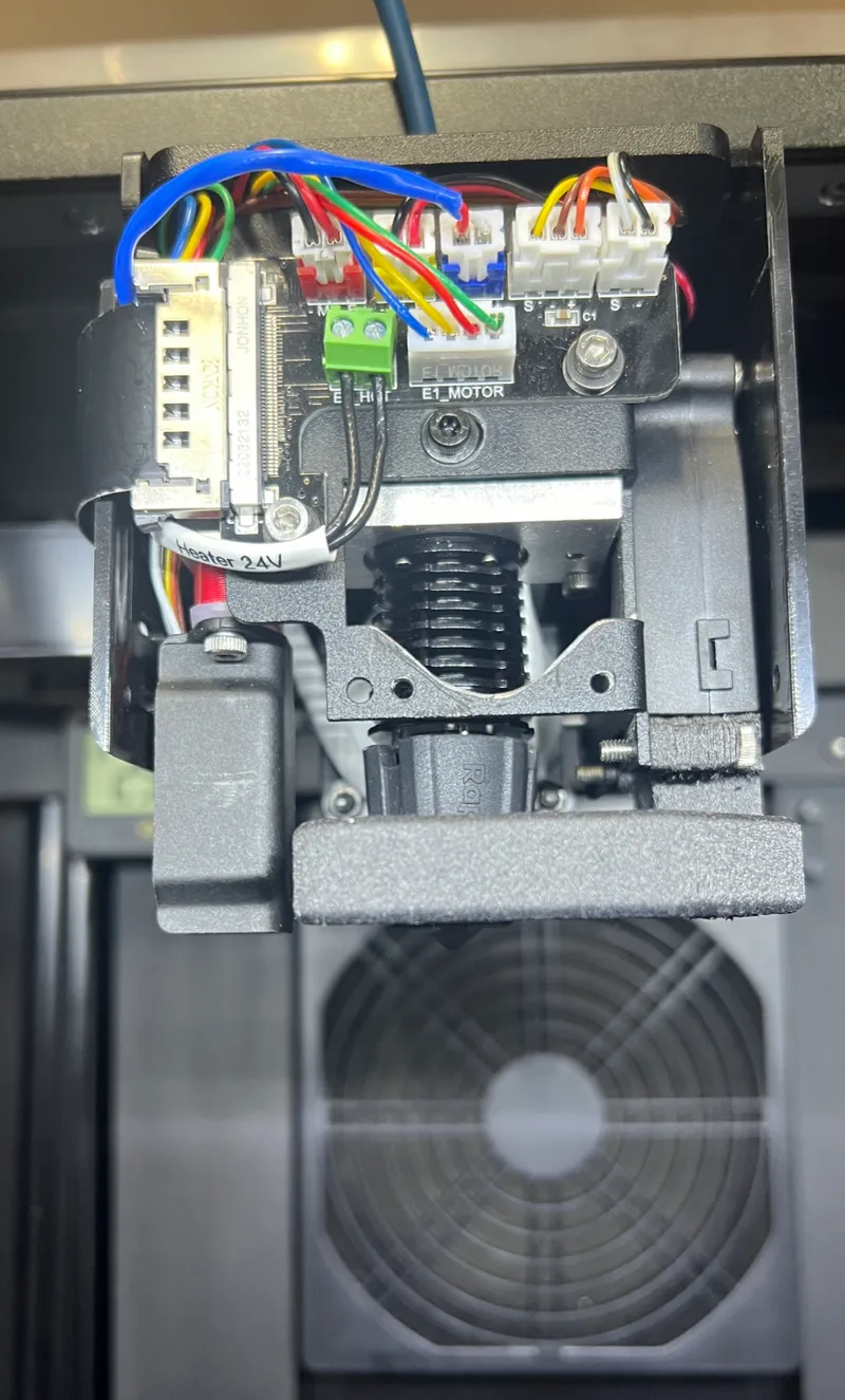
N. Install the BL Touch wires. No changes necessary. Final assembly should look like this.
O. Drill a 17 mm hole into the side of the lower cover so that you can access the knob to adjust tension on the filament feed. Attach the lower cover and the ribbon cable. I do not attach the upper cover since its only purpose is to guide the filament to the extruder. Instead I used a Bowden tube so that the fans can exhaust their hot air more easily.
Software Installation
P. Change the Z-offset of the build plate using the Leveling option on the printer. Increase the gap to something very large ~ 10 mm to avoid crashing the nozzle with the bed. Bigger gap is better so you don't damage your bed or Z-axis ball screws.
Q. Install a USB stick to the printer. Load the program original-configuration.gcode and run it. A file will now exist on the USB stick with that name which contains your current printer configuration. Save it in case you want to go back to original settings. You can open the .gcode file with a text editor such as Sublime or VS Code to make edits.
R. Load the program orbiter-v2.gcode and run it. The E-steps are now changed from the stock extruder to be compatible with the Orbiter V2. 100 mm of extruded distance should match the filament distance traveled when no nozzle is installed. If you ever want to go back to stock then pull the values from 'original-configuration.gcode' and replace them to match the stock extruder. You could read up on how to do more changes if you are so inclined.
S. Install your preferred nozzle. I use this torque wrench which is not cheap but is quite convenient.
You have completed all the steps. Enjoy printing again.
Take care not to perform any manufacturer provided updates to your machine's firmware. Those updates will assume stock hotend dimensions and cause your build plate to crash on the initial bed leveling step. If you want to do any updates re-install your spare stock hotend and increase the Z-offset to something like ~10 mm air gap again before swapping to the custom Rapido + Orbiter setup.
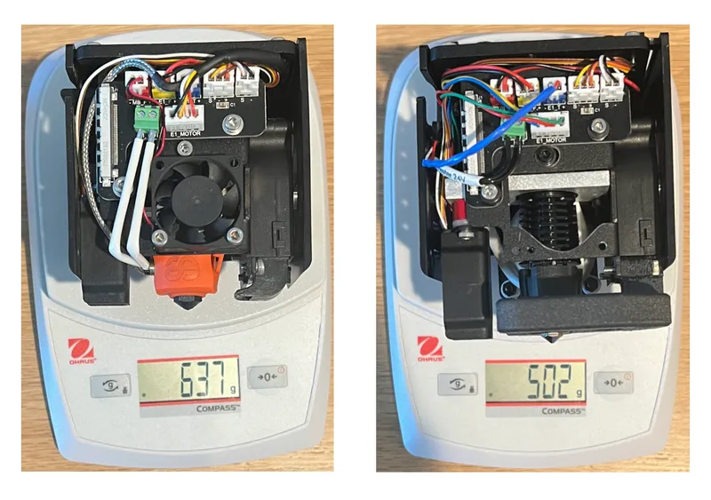
The upgraded setup is 135 g lighter than stock with:
- Better part cooling
- Better hotend cooling
- One handed nozzle swaps
- Improved visibility
- More consistent extrusions for a wider variety of filaments
- No need to swap assemblies based on filament material used
- Fully reversible and compatible with stock covers
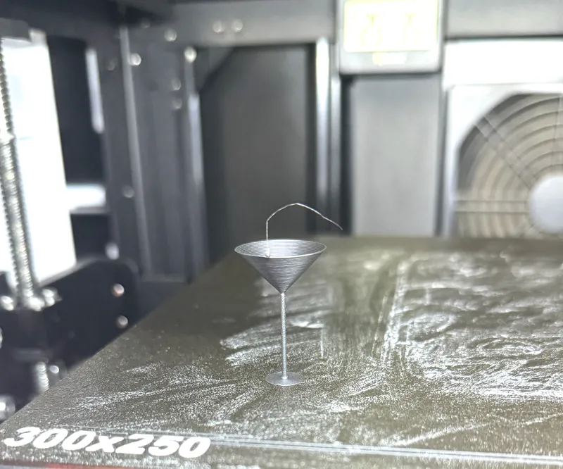
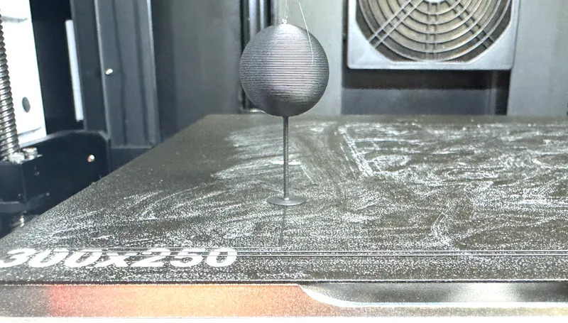
Some test prints to show exceptional part cooling, and extrusion consistency with a pin-support challenge demonstration in Qidi's matte black PLA.
Tags
Model origin
The author marked this model as their own original creation.


