Moonrover MK2

Description
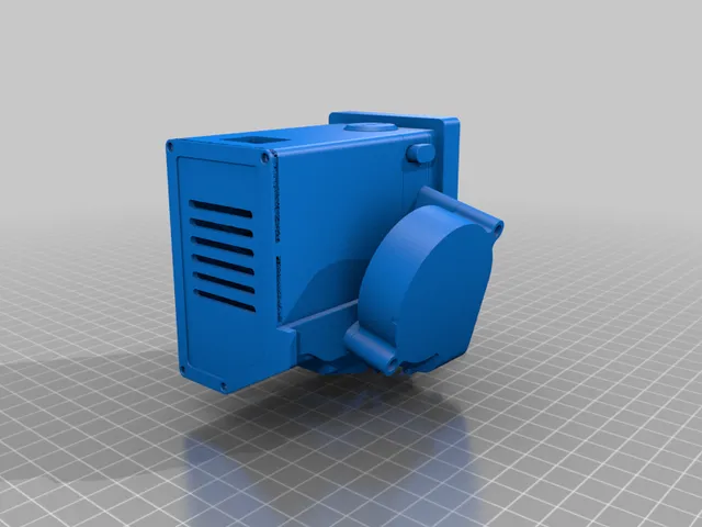
PDFReplaces the right thumb cluster with a trackball running a PMW3360 sensor on an arduino-based MCU. Connects to the keyboard directly via the original ribbon cable, no external wires to connect, and the keyboard (with trackball) is just as portable as the original keyboard.
BOM
- 19mm trackball (that I harvested from a handheld trackball mouse)
- 3x 2.5mm ceramic bearings
- ProMicro Board ATmega32U4 Leonardo 5V
- Any tiny arduino should work, but probably a good idea to avoid Seeeduino Xiao, as I was originally using that but couldn't get it to work as an I2C target
- Jack Enterprises PMW3360 breakout board
- I got the original from Jack Enterprises, but it looks like a new seller is making the exact same board
- (recommended) FPC 16P 0.5mm pitch ribbon cable breakout (I used this one)
- FPC 16P 0.5mm pitch ribbon cable
- The one that came with the Moonlander is probably too short when connecting to a breakout board
- I used this one
Assembly
Pin connections
Connect via the ribbon cable that's normally used to connect the right thumb cluster:
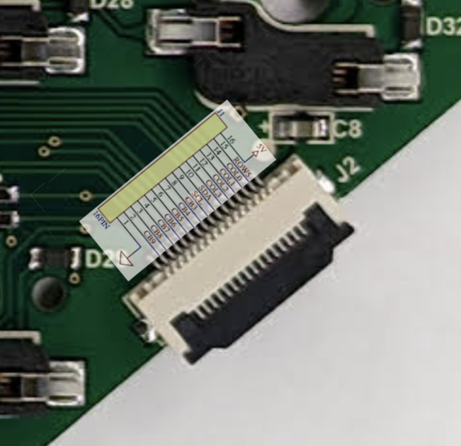
Then just wire all the wires between the boards correctly:
| Pro micro | Moonlander |
| SDA (2) | SDA (ribbon cable 10) |
| SCL (3) | SCL (ribbon cable 9) |
| RAW | 5v (ribbon cable 16) |
| GND | gnd (ribbon cable 1) |
CAREFUL: If you got the same “B type” ribbon cable as I did, pay attention that one side is actually reversed (e.g. 1 is 16). The breakout board I used conveniently has another side with all the pin numbers reversed.
| Pro micro | PMW3360 module |
| (NONE) | RS |
| GND | GD |
| (NONE) | MT |
| 10 | SS (Slave select) |
| 15 | SC (SPI Clock) |
| 16 | MO (MOSI) |
| 14 | MI (MISO) |
| VCC | VI |
Hardware
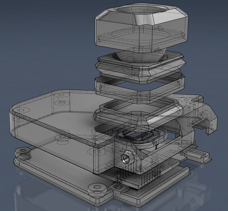
I tried to make things reasonably named, the “base” is the flat part at the bottom, and then the pieces for the trackball just stack together.
Everything is very very tight tolerances, but I swear it goes together.
The 2 parts of the base should be easy to fit together, and screws can hold them together. You can just kinda toss all the boards inside the base, as long as it closes.
The only board that's screwed down is the PMW3360 breakout board, the other 2 boards you just have to make sure that they don't short on each other (mine have a bunch of wires inside that keep things separated).
When putting together the trackball portion, notice that you'll need to put the ceramic bearings in, then put the ball in, then snap it together. Once you do this, it'll be pretty hard to get it to come back apart without some plastic bending, but I was able to use a spudger to pop them apart.
I did model in the little cutout to reuse the original thumb cluster's cable protection rubber like thing, I didn't actually model the thing as the only TPU I have probably wouldn't look nice, so I just reused the existing one.
Software
Code available on my github branch of QMK
Load the arduino sketch onto the pro micro
You'll need to either add the libraries to your library path, or install SunjunKim's PMW3360 library as the sketch uses that library
For the QMK side of things, it's a bit tricky. In my fork, most of the needed code is just in my keymap file, but I've also implemented a drag scroll with a custom keycode.
You'll probably want to read up on the QMK pointer device documentation, but there's basically just a few essential parts:
The I2C address is how the Moonlander will find the pro micro on the I2C bus.
#define I2C_TRACKBALL_ADDRESS 0x0A << 1The mouse data struct is how the pro micro and Moonlander will pass data between each other.
typedef struct __attribute__((packed)) {
   int16_t dx;
   int16_t dy;
} mouse_data_t;
You'll need to enable the custom pointing device in rules.mk
POINTING_DEVICE_ENABLE = yes
POINTING_DEVICE_DRIVER = custom
Then you'll need to implement the custom pointer init to start up the I2C bus and find the arduino
void pointing_device_driver_init(void) {
   i2c_init();
}
And finally implement the custom pointer report read to read data over I2C from the pro micro
report_mouse_t pointing_device_driver_get_report(report_mouse_t mouse_report) {
   mouse_data_t mouse_data = {0};
   i2c_status_t status = i2c_receive(I2C_TRACKBALL_ADDRESS, (uint8_t*)&mouse_data, sizeof(*&mouse_data), 100);
   if (status == I2C_STATUS_SUCCESS) {
      mouse_report.x = -mouse_data.dx;
      mouse_report.y = mouse_data.dy;
   }
}
Do note that you want to “rotate” the mouse report to make the movement more natural.
You may need to implement the other custom pointer methods like I did, but IDK if that's strictly necessary.
Tuning
Maybe it's just my sensor, but I could never get a perfect height for the ball from the sensor while printing things. It's supposed to have a 2mm tolerance, but that definitely wasn't true with mine. When the ball is too close to the sensor, it tends to jump around erratically (e.g. attempting to move left will move right in jolts, kinda like 2 steps forward and 1 back). When the ball is too far from the sensor, you just don't get input.
I've made the Trackball Bottom Lower and Trackball Bottom Upper as 2 pieces that friction fit together (a tolerance of 0).
To tune distance, the 2 bottoms should be able to interlock layer lines, so it's be best if you print both at the same layer height, and don't use dynamic layer heights (so you can end up w/ a zig zag pattern of interlocks between the 2). I do expect that someday this friction fit will fail, so I've include the Trackball Bottom Spacer which should slide over the bottom lower and the bottom upper could sit on it.
Legal
Obviously, all of ZSA's copyrights/trademarks still belong to them. I simply hacked this stuff into the awesome platform they made.
The “Moonrover” name is just a thing I liked, and hold no claims on it (it's only called MK2 'cause I did make a Moonrover MK1 and hated it for a few days before deciding this project was necessary).
I've included a .step file in the attached files to allow/encourage further modification of this model and would be happy if people want to contribute code suggestions in the github repo.
Tags
Model origin
The author marked this model as their own original creation.