Thank you!
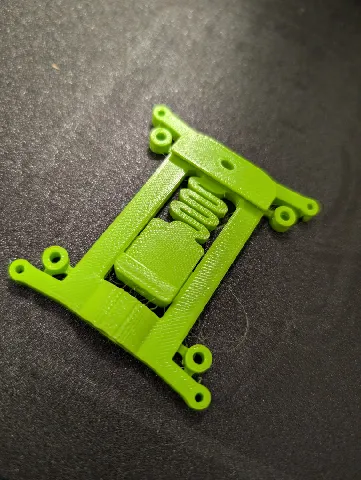
There needs to be about 5mm of standoff distance between where the Pi 4b meets the mount to allow relief room for the SD card and solder joints. Also, this won't fit on my DIN rail - it is about 1mm too narrow. This unfortunately will not work for me as-is, although I did solve the standoff issue by printing up some spacers of my own design. (edited)
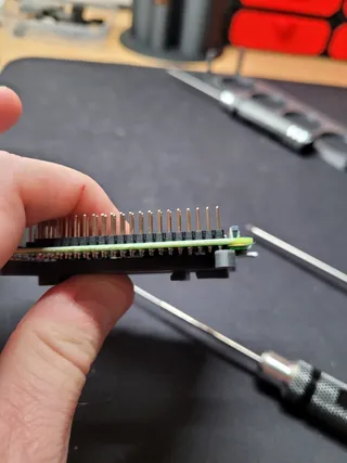
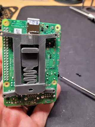
@JohnFleming_574221 Yeah, this was an incomplete file that i never corrected, the true file had built in snap off spacers to use. Sorry about that.
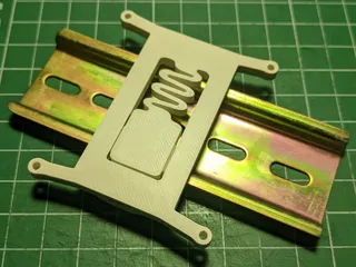
Same problem as someone else reported. Hook would not travel far enough to go onto the rail.
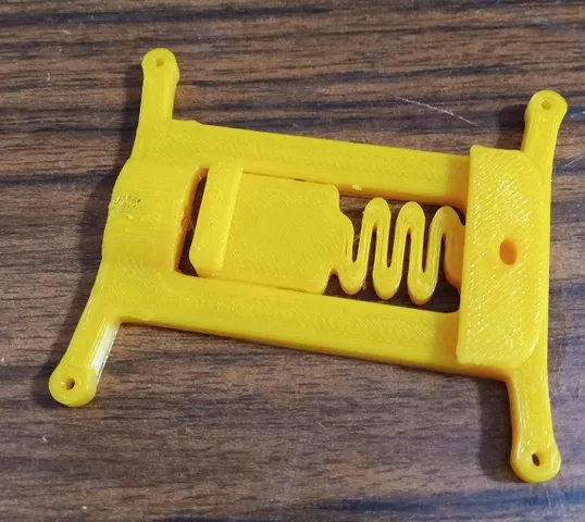
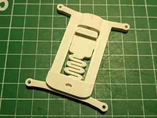
Cool design, I like that there is no assembly required.
I also ran into the issue that the "hook" ran out of travel before it would snap onto the rail on most DIN rails I tried (see circle). Only on one made out of thinner sheet metal it would barely snap on.
Printed at 0.2mm in PLA
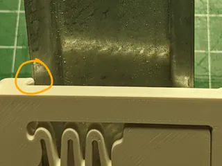
@vivaaprimaver_490937 what i thought, could be the manufacturer i got my rails from messed up.
@BBTECH https://no.rs-online.com/web/generalDisplay.html?id=ideas-and-advice/din-rails-guide there are several types of DIN rails. I think (also happened to me) that your rail is TS35 and the model was designed for TS32.
@Neville Thank you! Hope it will work well for you.
Really cool design. The spring mechanism is a good idea. But it's a bit too small, so it expands fully when clamped. ...I had to push it from the side onto the rail.
But great design. (edited)
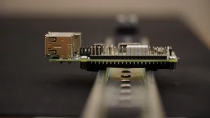
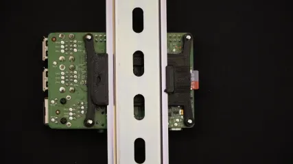
@3Dp_Jonathan purposely made to small, the springs will loose tension over time, i got a good two years out of this design before i noticed the pi's started to get loose.