v3 - Google Home Mini Speaker Housing - Retro Modern - with Swappable Face Plates

Description
PDFv3 UPDATE NOTES:
- This will likely be the final iteration of this project.
- The biggest change with v3 is that I have optimized the files to allow for the use of threaded heat inserts. Everywhere that screws previously threaded into plastic, now can thread into metal inserts.
- The Upper and Lower clamp pieces have been re-designed to minimize contact area with the Google Home and form an outward-facing curve. This should improve sound performance by directing sound out and away from the speaker rather than muffling it.
- The Front Plates now align with the Clamp pieces via three cylindrical guides. It holds fairly well just by friction, but magnets can still be used to give a more secure fit.
Google Home Mini Speaker Housing (with Swappable Face Plates)
Preface:
This model is a simple way to upgrade the aesthetic of your Google Home Mini speaker.
As far as I can tell, all of the Google Home/Nest Mini iterations should have the same dimensions and should fit this model. If yours does not fit, please reach out to me and I am happy to adjust the clamp tolerances for a better fit.
Note that there are two Front Plate files. One is plain, and the other has a radial cut-out pattern. Choose whichever one appeals to you!
See below for printing and assembly instructions. PLEASE READ EVERYTHING.
If you are searching for the assembly guides of previous versions (v1 or v2) of this project, I've uploaded the PDFs under the files section.
Non-Printed Parts:
- (x13) M3x12mm socket head screws (I bought this pack of 100 on Amazon)
- (x13) M3 Threaded Heat Inserts (I bought this pack of 100 on Amazon)
- If you don't want to use threaded inserts, I would suggest you either revert to v2 of this project, or simply use larger screws and thread into the plastic.
- (x9) 6x2mm cylindrical magnets (I bought this pack of 400 on Amazon)
- Superglue/hot glue (I recommend superglue)
Printing:
Unless otherwise specified below, I used the following settings to print all of the parts:
- 15% gyroid infill
- 0.16mm layer height
- 3 walls
- No supports
- Print all models in the default orientation of their respective STLs.
- The tolerances should already provide a snug fit for all of the parts, but you may need to play with the horizontal expansion settings in your slicer if the parts are not fitting together well.
Additional Print Settings and Orientation Notes:
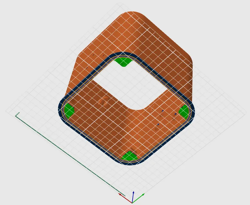
- Main Housing:
- Will need supports in four locations. This is a view from the bottom to show where the supports need to go (supports depicted in green). I would suggest painting on the supports in each of the four locations to prevent them from auto-generating in other areas where they are not needed.
- Front Plate:
- If you would like the texture of your buildplate to be visible/facing outward when assembled, print with the default orientation of the STL.
Assembly:
Pre-Assembly:
- Using a heat press, soldering iron, or other method of your choice, insert all 13 of the threaded heat inserts into the corresponding 4mm holes:
- 3 on each leg
- 1 on the back of the upper clamp
- 2 on the back of the lower clamp
- 4 on the main housing where the rear plate attaches
- Using superglue, glue the magnets into place on the Front Plates and the Clamp pieces. Make sure the polarities are oriented correctly so that the front plates hold against the clamp pieces.
Steps:
- Step 1:
- Using six of the M3x12mm screws, screw the legs onto the Main Housing.
- Step 2:
- Clamp your Google Home Mini device between the upper and lower clamp pieces.
- Notes:
- The power cable feeds through the cable cut-out found on the lower clamp piece.
- It is recommended to keep the power cable plugged into the Google Home Mini (but not plugged into the wall) during this step, as it makes alignment easier.
- Step 3:
- Fit the front plate of your choice (plain or patterned) onto the front of the clamp pieces. The arrows on the back of the front plate should point in the same direction (upward) as the arrows on the sides of the upper clamp.
- Notes:
- The embedded magnets in the front plate will align with the magnets in the upper and lower clamp pieces. This will ensure a snug fit but allow for easily switching between the different front plate style options (plain and patterned)
- Step 4:
- Feed the power cable of the Google Home Mini through the front of the main housing and out the back. Insert the Google Home Mini clamp assembly into the front of the main housing.
- Viewing the main housing from the back, use three of the M3x12mm screws to secure the clamp assembly to the main housing.
- Notes:
- Make sure the arrows on the upper clamp piece are pointing up, the same direction as the arrows on the interior of the main housing.
- There is a sacrificial layer on the three screw entry holes on the main housing. These are there to help print without supports, and can easily be punctured/removed after printing to allow the screws to pass through and connect to the clamp assembly.
- Step 5:
- Fit the rear plate onto the back of the main housing. Using the remaining four M3x12mm screws, secure the rear plate to the main housing.
- Notes:
- Make sure that the counter-sunk holes are facing outward.
- The rounded cut-out on the rear plate should be at the bottom, allowing the power cable to feed through and exit the main housing.
- Optional Step:
- On the bottom of each foot of each leg, there is a small rectangular cut out. A thin strip of hot glue can be placed in these cutouts to give the feet some grip and keep the whole thing from sliding around. For a slightly more refined look, you can also superglue thin strips of rubber into the slots. (I bought this strip of rubber on Amazon).
- Assembly complete!
Overall Dimensions:
- H8.125in x L6.9in x W5.625in
Additional Notes:
- The pictured model was printed on my Bambu Lab P1P using Bambu Matte Black and Matte White filament.
- This model is not for commercial use. If you are interested in selling your 3D prints of my models, please refer to my Printables Club.
- If you like this design, consider leaving a tip! I'm a university student, so anything helps!
Tags
Model origin
The author marked this model as their own original creation.


