" Anycubic Key " Proximity Sensor height tool & Extruder Tension disengage tool & for Kobra 2 , Kobra 2 Max , Kobra 2 Pro , Kobra 2 Neo , Kobra 2 Plus

Description
PDF" Anycubic Key " 2 Tools in One
Extruder Tension disengage tool & Proximity Sensor height tool.
- Disengage tool allows you to disengage extruder tensioner. Gives you the ability when you load your filament all the way without having to pull back on leveler. Frees up a hand allows to load filament with ease. Great for dryer box setup.
2. Proximity Sensor height tool set sensor to proper factory height. Allows for quick check and set.
Print Instructions:
- 100% infill
- 9min print.
- no supports
- print with any material you like. quick and easy
How to use tool.
1. Disengage tool:
- Pull back on lever and insert. Has safety stop so can't install too deep. Key is bidirectional can be inserted either way.
2. Proximity Sensor height tool:
- How to check
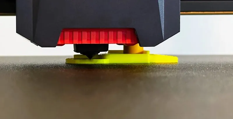
- Works best with power off or motors disabled manually lowering the print head down by rotate the Z axis rod by hand onto the Key.
- To lower turn Z Axis Rod Counterclockwise. To Raise turn both Z Axis Rods together in Clockwise direction.
- Note: You can also do with power on motors and drive down. But with power off or motor disabled there is no chance of crashing.
- Slide Key in from back if already lowered. Key has built-in sensor hard stop & nozzle hard stop so it can easily be place.
- The nozzle should be on the lowest part of the Key in front of Anycubic Logo. The Sensor should rest flush on back of the platform above that. See Above pics for more detail.
- If your sensor is the right height power back on and home the printer.
- If you find your sensor is the incorrect height you will need to adjust.
- Use this guide to adjust sensor.
- Anycubic Kobra 2 Series:Proximity Switch Replacement Guide | Anycubic Wiki
- Rerun Auto Bed Leveling after complete.
***************************************************************************************
Prerequisites For Both Fixes Below:
Update to latest firmware.
- Old firmware had known issues and should be upgrade to latest could be causing your problems.
Remove Filament or a least make sure Nozzle is clean.
- Not doing this will throw off all your measurements your printer takes.
Check tightness of your X gantry wheel make sure everything is tightened properly.
Verify Initial Printer Setup is Correct:
Verify your X-Gantry is Square
- Directions to do this here https://www.printables.com/model/653220-the-rook-anycubic-kobra-2-kobra-2-pro-kobra-2-plus
Verify you don't have any high and low spots in your bed verfiy it is trammed.
- Directions to do this here https://www.printables.com/model/730729-anycubic-dial-indicator-mounts-for-kobra-2-max-kob
******************************************************************************
******************************************************************************
How To Fix Extruder Head Crashing into Bed Issue.
*************************************************************************************************
Step 1: If recently changed nozzle. Make sure it is tightened back to proper height.
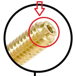
- If you are changing to new nozzle, make sure your nozzle is the correct kind and is a 1 for 1 swap. The Factory Nozzle has a offset at the end of nozzle and is property. You will need this style nozzle if you but new. Standard nozzle sold after market do not have this offset and are straight. Installing wrong nozzle will cause improper height and cause nozzle leaks.
- Anycubic Kobra 2 series:Replace Nozzle Guide | Anycubic Wiki
- To do this make sure to heat the heat block above max temp pf printer. This will cause thermal expansion and then tighten. when the heatblock cools down. The heatblock will contract and nozzle will be very tight.
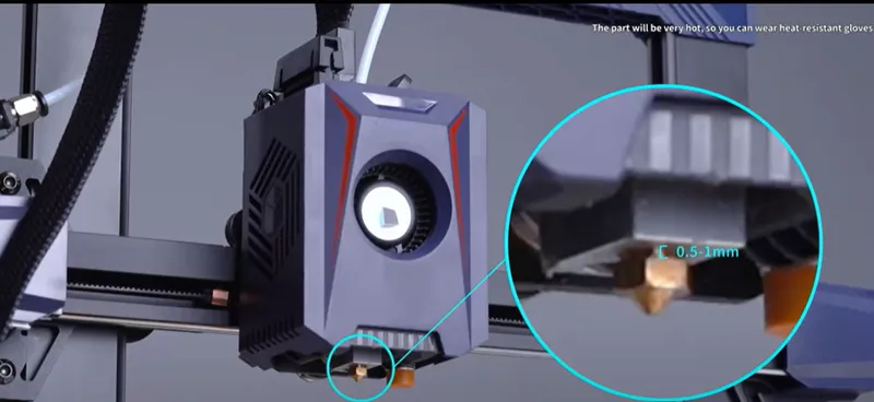
Anycubic states gap distance between heatblock and nozzle tolerance to be .5mm-1mm between the headblock and nozzle. I have 3 stock unmodified print heads I measured my tolerance to be between 0.7mm-0.8mm
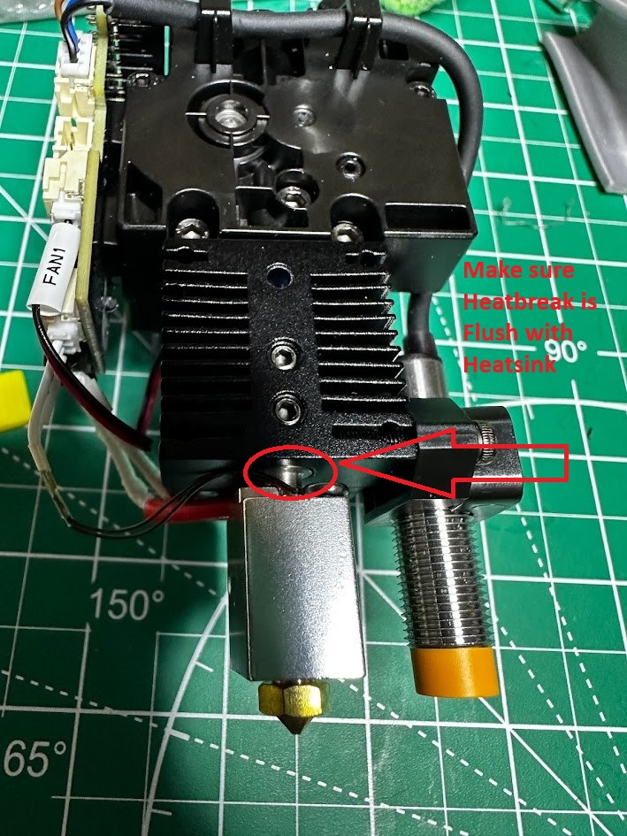
Step 2: Check your Heat break is Flush with Heatsink.
- Verify the 2 grub screws have not come loose on heatsink, And Heat break is still flush with heatsink.
- If you have took the heater block & heat break out of heat sink. Make sure it is all the way flush with each other when you reinstall.
Anycubic Kobra 2 Series:Hotend Replacement Guide | Anycubic Wiki

Step 3: Check make sure PTFE tube is correct: If you recently changed your PTFE tube with a new one and it appears to long. You will need to heat up your hot end and clean out the melted PTFE and filament keeping your new PTFE tube from going all the way down in your heatbreak. To make a new PTFE tube or to verify length of PTFE tube use this Jig premeasured to factory length. Hotend PTFE Cutter Cutting Jig For Anycubic Kobra 2 Series Printers
Step 4. Check your proximity sensor take a metal wrench and place near the bottom of the head of sensor. Make sure the blue light turns on inside the extruder head. If it does your proximity sensor is working.
- If Blue Light is coming on and print head is still crashing into bed after you have set the factory height of proximity sensor,
- Means the proximity switch is working but the signal wire is not getting back to mainboard. Could be faulty print head cable, bad breakout PCB on print head, bad mainboard. Electrical Schematics at bottom of post to help you troubleshoot.
- If Blue Light is not coming on. After you checked with metal wrench
- If not take the extruder head cover off with the two bolts in back of head. Check the proximity switch wiring inside the print head for damage or improper insertion.
- Disconnect the proximity Sensor from Print Head PCB. with Power on Check for 24v to PCB from mainboard.
-
- Make sure the connector is fully inserted on breakout PCB located on top of printhead. Quick validation is completely remove it and reinsert.
- Make sure the connector is fully inserted on the mainboard located under printer. Quick validation is completely remove it and reinsert.
- Check Cables Continuity with power off with Electrical Schematics at bottom of post to help you troubleshoot.
If Proximity Switch is Intermittently not working. Work on one side of bed and not the other.
- Quick and Dirty Check of Ribbon Cable, PCB Connector
- With the print head all the way to left and power on disabled motors if not done already
- Take a metal wrench and hold under the proximity switch to turn on blue light in print head.
- Now move the print head from far left and right with metal wrench under proximity switch.
- Repeat a couple times.
- See if blue light turns off any while moving. If it does indicates a bad cable or pcb connector on printhead.
- Still can't get it to go off. You can manually move and lower printhead to location it was crashing to check cables and connector.
- While you got the print head in that location manually check with Anycubic Key to see if your bed is warped or low in that spot.
Risker Method.
- Rerun where your extruder head was crashing.
- Right before it crashes power off your printer with the power switch.
- This will stop printer from crashing so you can do your checks.
- Power back on leave printer head in almost crashed state.
- Take a piece of metal under the proxy validate it is still not making leave it there while moving around your ribbon cable, press on top connector, wiggling the wire on that is connected to proximity switch.
- You're checking for damage in the cable or connector.
- While you got the print head in that location manually check with Anycubic Key to see if your bed is warped or low in that spot.
Step 5: Make sure your updated to latest firmware.
Step 6: Set the factory proximity switch height with steps above.
- If you didn’t already print one move to next step (Print one after you fix issue)
- If your down hard and can't print take your cover off the proximity switch should be set to where there is only one thread showing on top of proximity sensor mount. this should get you close to proper height get you up and going. After that use Anycubic key to move to factory height.
Step 7: Rerun Auto Level and Dial in your new Z-Offset
Here are some models to help you with that.
- Anycubic Kobra 2 Max Bed Level First Layer Calibration Squares Aligned with Bed Screws and Brim Test
- Anycubic Kobra 2 Pro Bed Level First Layer Calibration Squares and Brim Test Also works with Kobra 2 / Kobra 2 Neo
************************************************************************************************
How to Calibrate Auto Bed Level Sensor (LeviQ 2.0)
This Fixes Following issues.
- Bed Scratching Issue:
- Prompt "The module is abnormal. Please calibrate the position of the nozzle and module”
*************************************************************************************************
Step 1: Make sure your updated to latest firmware.
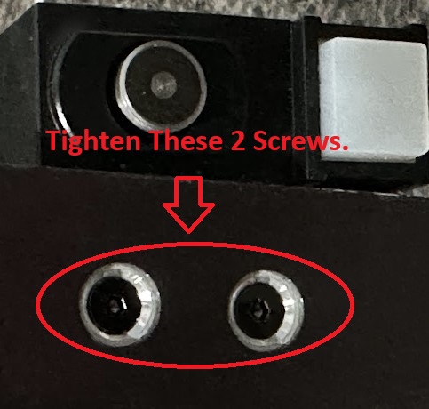
Step 2: Check Sensors Mounting Bolts
- Take the bed sheet off
- Tighten the two bolts that hold on your auto leveling sensor.
- Turn them till you can’t turn them no more. Without striping them out.
- They have locknuts holding on the sensor they been known to get loose from shipping.
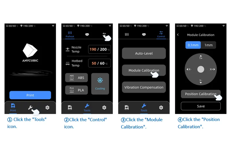
Step 3 Run Module Calibration
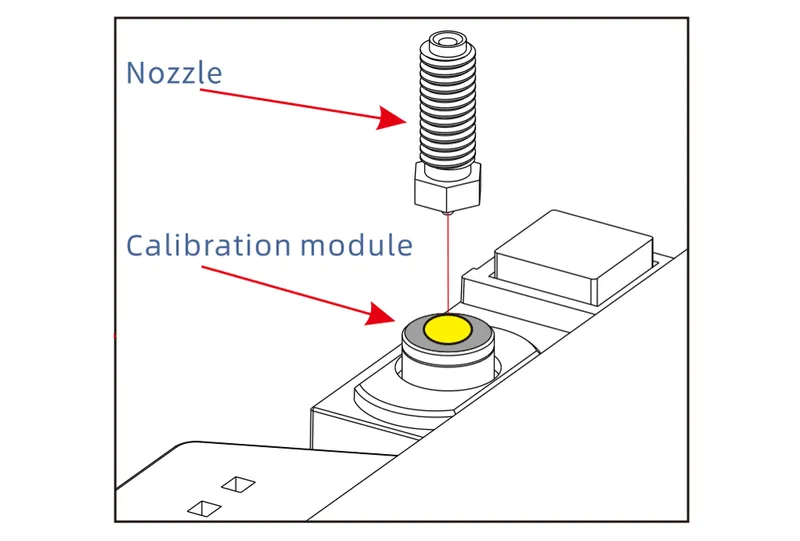
- Make sure your nozzle is center of LeviQ 2.0 Auto bed leveling Sensor.
- Make sure Nozzle is clean before running this.
- Best practice to remove filament from print head and clean the nozzle tip manually before running this. For best results. (Can allow machine to wipe nozzle with filament in it but sometimes it doesn't to a good job leads to inaccurate results)
- Click on the "Tools" ➞ "Control" ➞ "Module Calibration" ➞ “Position Calibration.”
- If not, it might be due to the nozzle not making contact with the calibration module, resulting in an error. You can adjust the nozzle to be above the center of the calibration module using the interface's movement distance unit and X/Y axis movement directions. After adjustment, click "Save," and then perform the auto-leveling process once again.
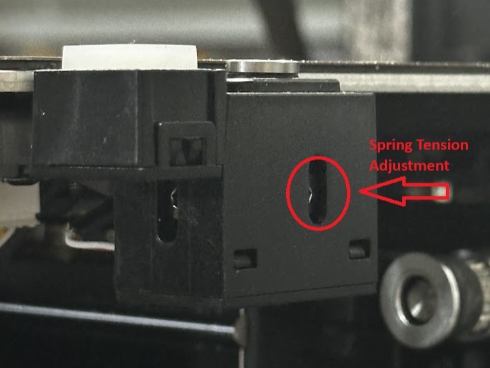
Step 4: Check and adjusting Sensor's Spring Tension
- The sensor is spring loaded and should move up and down freely when being triggered.
Make sure that it does. It should pop up on its own once released from being held down. - If you need to adjust the sensor's spring tension, you can do so by with hex screw on back side of sensor looking at the back of printer.
- Turning it counterclockwise decreases the tension, turning it clockwise increases the tension.
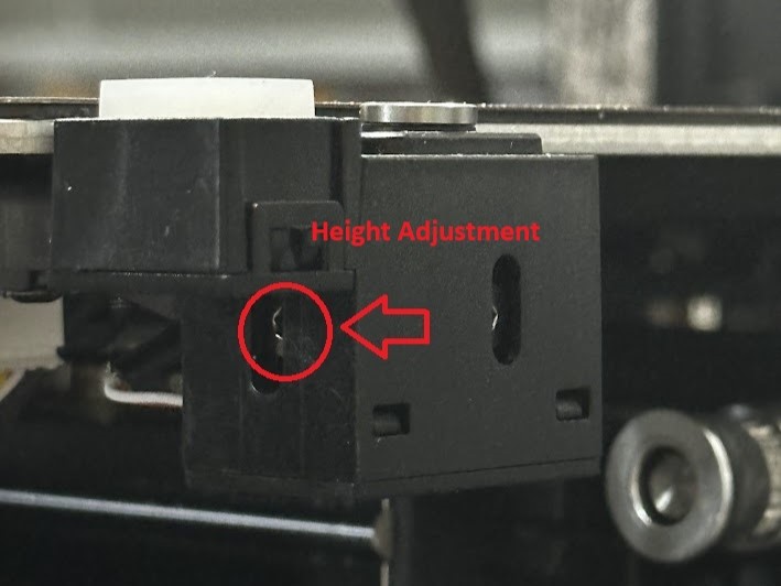
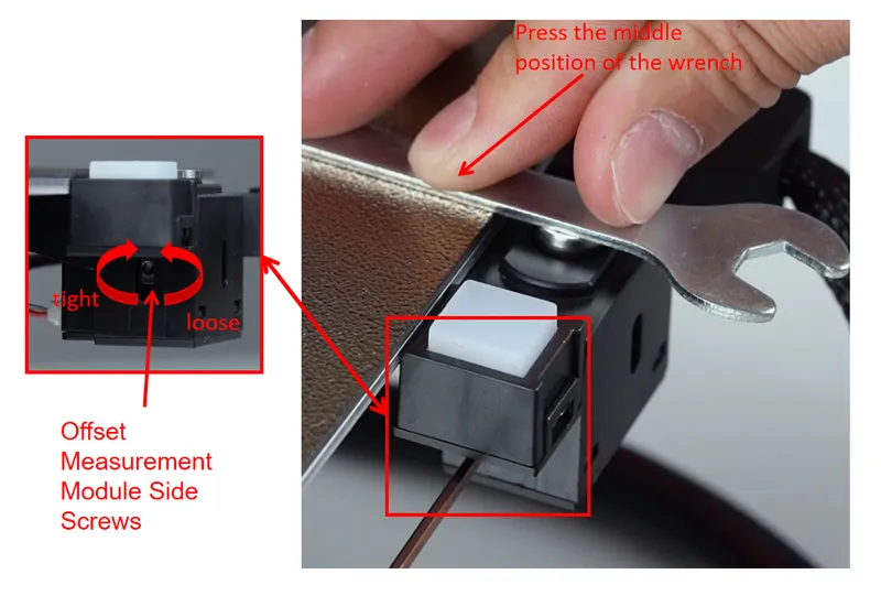
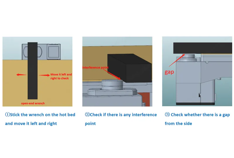
Step 5 Check and Adjust Sensor Height
- Put PEI sheet back on the bed.
- The height of the sensor's surface should be exactly the same height as the topside of the PEI build plate.
- You can check if this is the case by placing a flat object (like the open-ended wrench that came with the printer onto the build plate, let it stick out a bit so that it reaches above the sensor and then carefully move it across the sensor from the side.
- While holding the tool in this position across the sensor's button, now loosen M2 hex screw located on the left side of the level sensor to adjust the height of sensor. Adjust it till it touches the bottom of your tool or flat edge.
Step 4: Clean the ABL Sensor (LeviQ 2.0) internals from debris
- Refer to the link below to clean internals the ABL Sensor (LeviQ 2.0)
Step 6: Rerun Auto Level and Dial in your new Z-Offset
- Here are some models to help you with that.
- Anycubic Kobra 2 Max Bed Level First Layer Calibration Squares Aligned with Bed Screws and Brim Test
- Anycubic Kobra 2 Pro Bed Level First Layer Calibration Squares and Brim Test Also works with Kobra 2 / Kobra 2 Neo
Advanced Troubleshooting Steps If above Steps did not fix your issue with ABL Sensor (LeviQ 2.0).
Step 7. Check for Poor Wire Connection
- Turn off the printer.
- Before proceeding with troubleshooting, make sure to turn off the printer and disconnect the power to ensure safe operation.
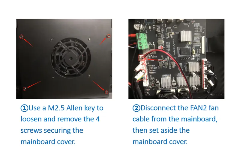
- Disassemble the Cover on the Mainboard
- Use a M2.5 Allen key to loosen and remove the 4 screws securing the mainboard cover.
- Disconnect the FAN2 fan cable from the mainboard, then set aside the mainboard cover.
- Check proper installation reconnect the cables.
- Reconnect and reinsert the cables at both ends of the calibration module. One end should be connected to the mainboard, and the other end to the bottom of the heated bed aluminum plate.

Step 8: Check for a Hardware Issue
This troubleshooting step requires a certain level of electrical knowledge and measurement equipment.
- With the machine powered on, set the multimeter to the 20V DC range (Note: Different multimeter models might have different range settings, so adjust according to your specific model, ensuring the range is greater than 3V).
- Place the black probe (negative) on the second PIN from the top downwards on the mainboard calibration module port and place the red probe (positive) on the first PIN from the top downwards, then measure whether the PINs on the mainboard have a voltage of 3.3±0.3V.
- If the measured voltage is within the normal range, then the mainboard is functioning correctly. If the measured voltage is outside the range, it might indicate a mainboard issue, and you may need to consider replacing it.

Step 9: Check continuity of Cables and PCB on Printhead.
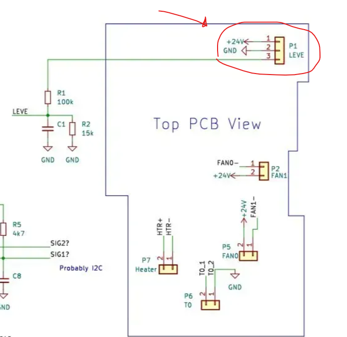
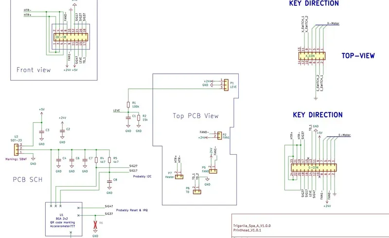
Electrical Schematics for Troubleshooting
Step 7. Submit After Sales Ticket
The above troubleshooting methods did not resolve the issue. Recommend that you create an after-sales ticket to provide the after-sales engineer with feedback on the previous inspection process and results.
After-sales Ticket Submission Page
Model origin
The author marked this model as their own original creation.


