Guide to Adding a Second Aux Part Cooling Fan on a K1 Max
Description
PDFGuide to Adding a Second Aux Part Cooling Fan on a K1 Max
Parts List:
- Delta brand fan from Digikey http://bit.ly/4aXW0Jd (if you purchase two of these to replace the original fan with this upgraded quieter fan the you will need the heat set inserts)
- (M3 x 5.7 heat set inserts x 3) (https://bit.ly/3O4mNJT) or any insert that 4.6mm od
- 1M of two-core wire from Digikey https://bit.ly/3Hiogsj
- Electrical tape and/or heat shrink
- Flux core solder
- Command strips (https://bit.ly/3RVPkT5)
- Isopropyl alcohol
- Cable ties (2.5mm x 100mm) (https://bit.ly/3Hh966r)
- Printed parts in ASA or ABS (links provided)
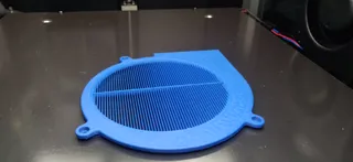
- Optional fan guards (https://bit.ly/3TYPcVm) (M3x5.7 heat set inserts x 6 any insert that 4.6mm od (https://bit.ly/3O4mNJT)) (M3 x 8mm cap head screws(https://bit.ly/3S5pWdQ)) Print two of these in ASA or ABS
Tools Needed:
- Side cutters
- Wire stripper
- Soldering iron
- Lighter or hot air gun
- 7mm socket or spanner
- 2.5mm Hex key
- 2.0mm Hex key
- Small round file or 3mm drill bit
Preparation:
- Print the required parts in either ASA or ABS.
- Lower the print bed by 100mm to facilitate part removal.
- Unplug the fan, unscrew it, and remove it completely. Open the wire guides.
- Install heat set inserts in the fans if required.
- Attach command strips to the back of the new/left fan.
- Turn off the printer!
Instructions: Ensure the Printer is Off!
- Cut the original aux fan cable about 2 inches or 50mm from the connector.
- Strip about 1/2" or 1cm of insulation from both wires.
- Repeat the stripping process for the new fan and the second fan if applicable, ensuring 1/2" or 1cm of exposed conductor on the red and black wires.
- Split the new cable, strip 1/2" or 1cm of the insulation, and add a length of heat shrink tube to each exposed conductor.
- Take note of the wires with the white/grey dotted line running down its length the original fan wire and the new wire were adding will have the same mark down one conductor this is the positive.
- Take the positive from the fan (red for new fan),positive of the connector and the positive of the new wire and solder these together then heat shrink or tape.
- take the negative wire from the fan (black for new fan), negative of the connector and the negative of the new wire were adding and solder these together then heat shrink or tape.
- you should now have wired the new fan extension wire in parallel with the original fan.
- Remove the cable guide cover closest to the fan connector and route the new cable to the top, then replace the cover.
- Remove the cable guide cover on the top right, route the new cable across and over the top of the centre bed support, ensuring it tucks into a gap behind it, and then replace the cover.
- Remove the cable guide on the top left, route the new cable through and out the end, and behind the stepper motor. Replace the cover and allow the cable to dangle down for now.
- Attach the right side fan to the side panel and clip the wires into the guides. If using the original fan, it should go back on as it came off. If necessary, file out the holes to allow the new fan to bolt on. Use a 3mm drill bit to elongate the hole until the fan fits. It shouldn't be more than 1mm out on all the holes.
- Remove the print surface and bed to allow the removal of the cable bracket that holds the wire for the bed level sensors and heated bed.
- Using a 2.5mm hex key and a 7mm socket or spanner, remove the 4 screws holding the bed on. Be careful not to lose any of the 4 spacers for the bed.
- Snip the cable tie on the metal bracket that holds the cable in place and prop the bed up to access the 3 screws that hold the bracket in.
- Remove the screws and replace with the printed bracket, adjusting the path of the cable for the levelling sensors if necessary.
- Reinstall the bed, this can be tricky to get all the spacers in place start at the back left place a spacer, drop the screw in and line it up, then drop through the hole in the sensor add the nut to the bottom leaving it very loose. do the same with the back right then do both front two at the same time placing the spacers down and lowering the bed.
- Tighten the bed screws so they are barely tight and back them off a quarter turn so the bed can still wiggle.
- Try to find the central resting position of the bed by pushing it left to right and front to back, then tighten the screws so they just start to feel tight. Once snug, turn the nut 1/2 to 3/4 of a turn for the correct tightness.
- Temporarily unplug the aux fan, switch the printer back on, reapply the print surface, home the bed, and lower it all the way to the bottom 304mm ish .
- Tuck the cable into the small gap beside the bed temporarily.
- Mark the edge of the LiDAR calibration square bracket nearest to the back onto the print surface with a marker pen or tape, lift the print surface up and move it over to the left being carful not to get the tab at the front in the screw thread see picture, make sure the print surface is square to the bed and not quite touching the side of the printer a 1/8" or 3mm gap will be sufficient
- Move the bed to Z=174mm using fluid or Mainsail. If your machine is not routed, you'll need to move the bed all the way to the lowest position, then up 131mm. You can do this by navigating to the movement/temp tab and pressing Z up 30mm x 4, 10mm x 1, and 1mm x 1.
- Attach the fan by peeling off the adhesive protection on the command strips, then stick the fan to the side of the printer, ensuring it stays towards the rear of the printer behind the mark that was made on the bed, about 3/8" or 9mm. Use the print surface to keep the fan level and at the correct height, then press gently onto the side panel. Once stuck and happy with the position, support the panel from behind and press firmly for 30 seconds to secure the adhesive.
- Lower the bed by 30mm and return the print surface to its normal position. Wipe off the mark with isopropyl alcohol (IPA), and zip-tie the cable into its final position, ensuring it isn't stuck under the bed as this would stop the bed from moving down during levelling and homing.
- Move the bed all the way to the bottom again and turn off the printer.
- Trim the new cable so it has about 1" or 25mm sticking out from being tucked behind the stepper motor. Ensure the fan wires can reach to be joined (it may be easier to take the cable back out of the cable guides to strip and solder), and make the final solder connection. Refer to steps 2-7, bearing in mind there are only two wires this time.
- Tuck the fan wire behind the new fan duct as you install it and plug in the fans. If you have printed the fan guards, fit those now.
That's it! Happy printing!
Model origin
The author remixed this model.
Differences of the remix compared to the original
Remixed the outlet for use on the left hand side to direct the flow of air more into the centre of the printer


