Ball adding machine / Calculator (print in place, no supports) V1.0


Simple adding machine, that adds numbers up to 64.
Also works as printer torture test for tolerances.
In the contest Counters
155
254
3
4893
updated January 2, 2024
Description
PDFThis is simple adding machine.
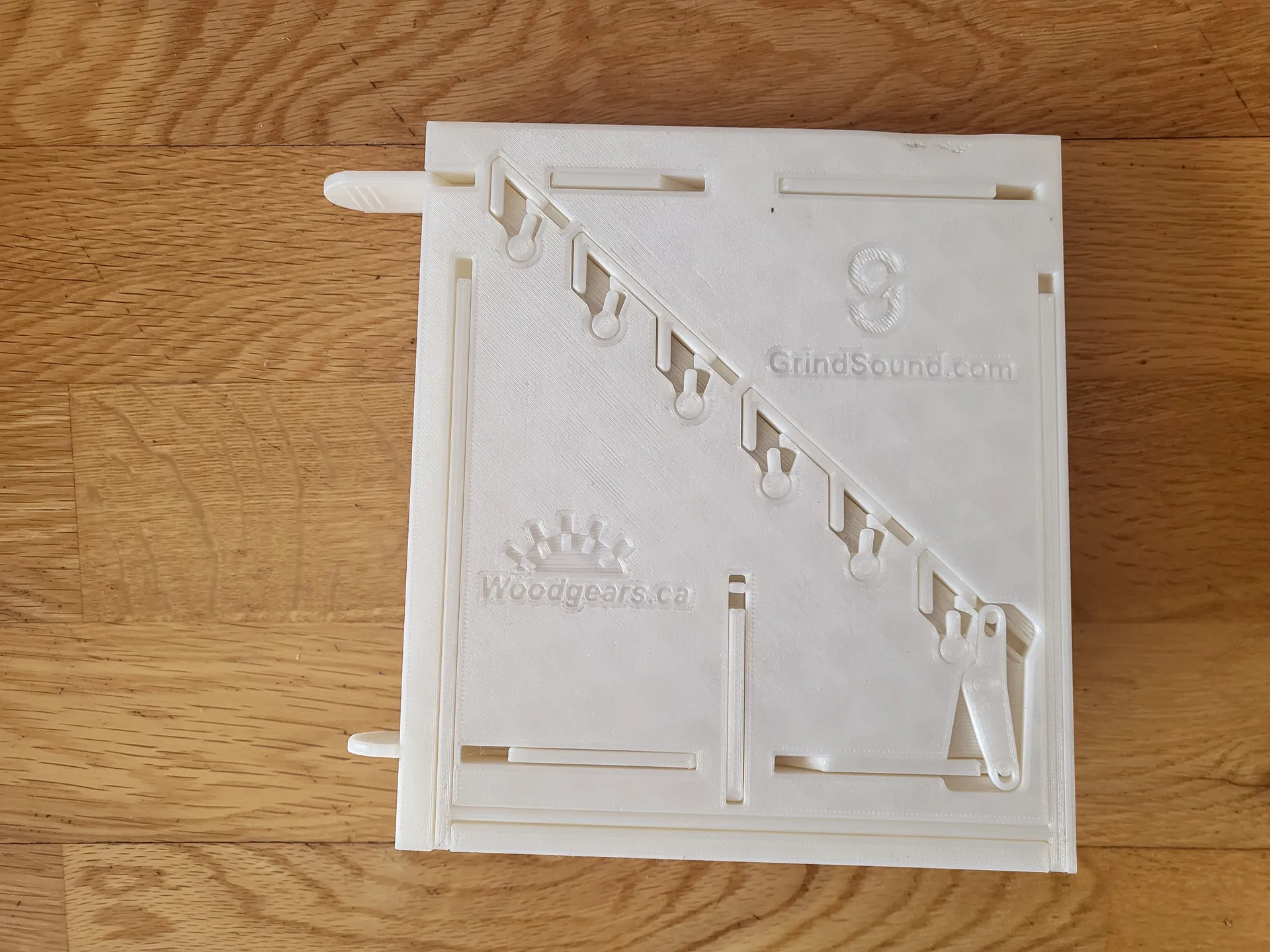
Main design of idea and some mechanical principles are taken from Canadian woodworker https://woodgears.ca/
I first saw his marble ball counting machine made out of wood about 10 years ago. Now I decided to try to create one for 3D printers, that would be print in place and could fit on my Prusa Mini.
Because of size limitations this calculator uses 9mm steel balls instead of glass marbles like in original wooden machine. Some day I will create larger, split in parts version for classical marbles.
How it works
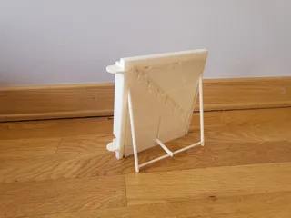
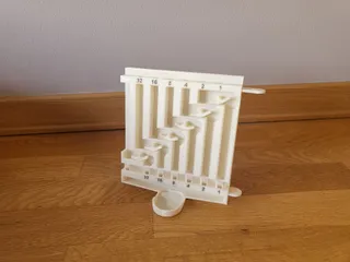
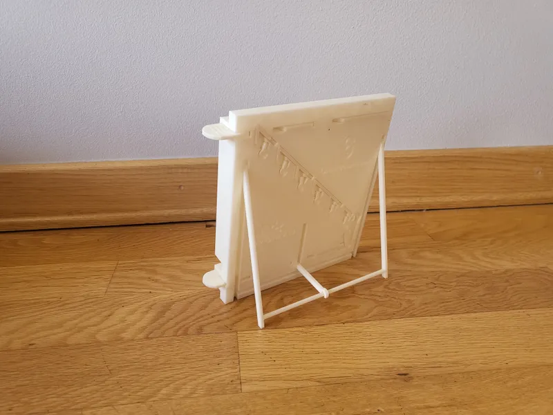
- Pull out stand legs and support, so calculator can stand in correct angle.
- Pull out and push in bottom handle to reset all levers.

- Push in top handle.
- In start setup:
- top holes must be closed,
- all levers flipped to the left,
- bottom holes must be open
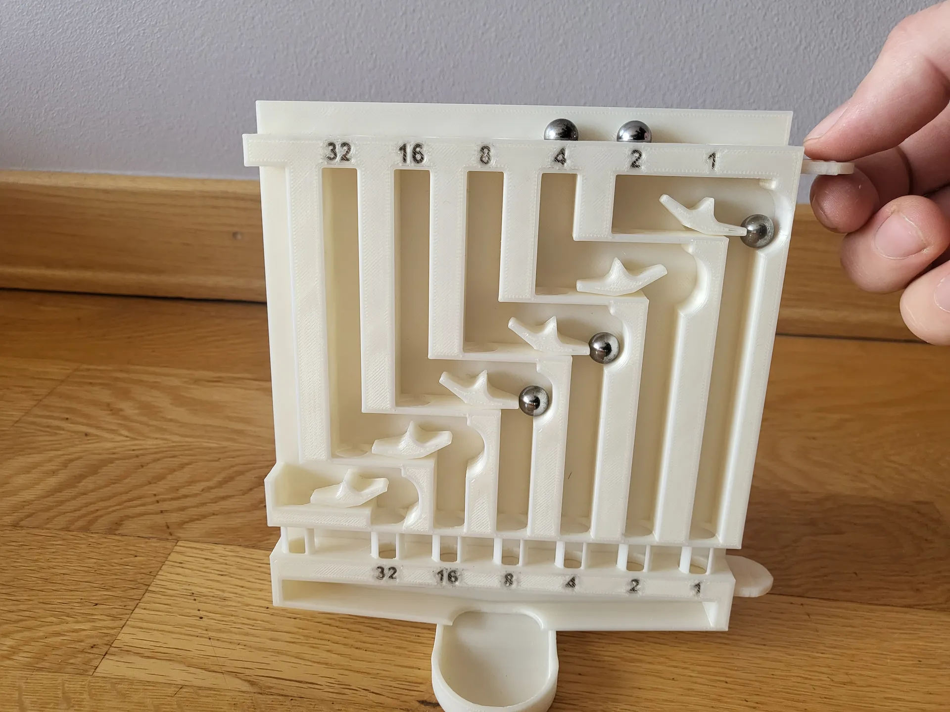
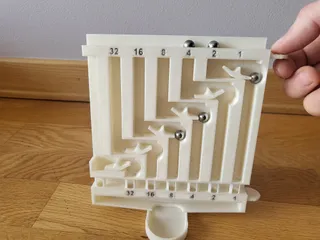
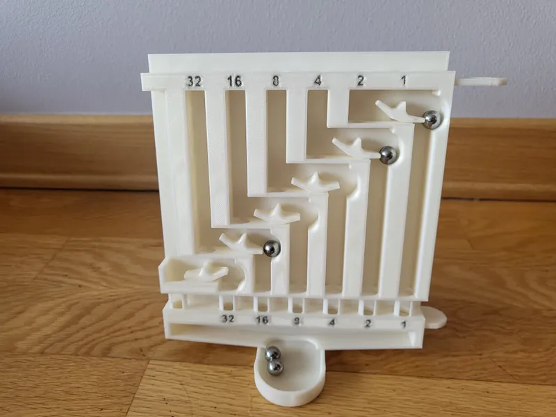
- Place first number (1 - 64) on top. For example number 13 must be set as 8, 4 and 1
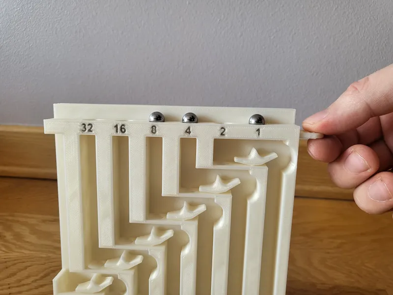
- Pull out top handle and let all balls fall down on levers.
- Push top handle back in and place second number. (for example 6 - as balls 4 and 2)
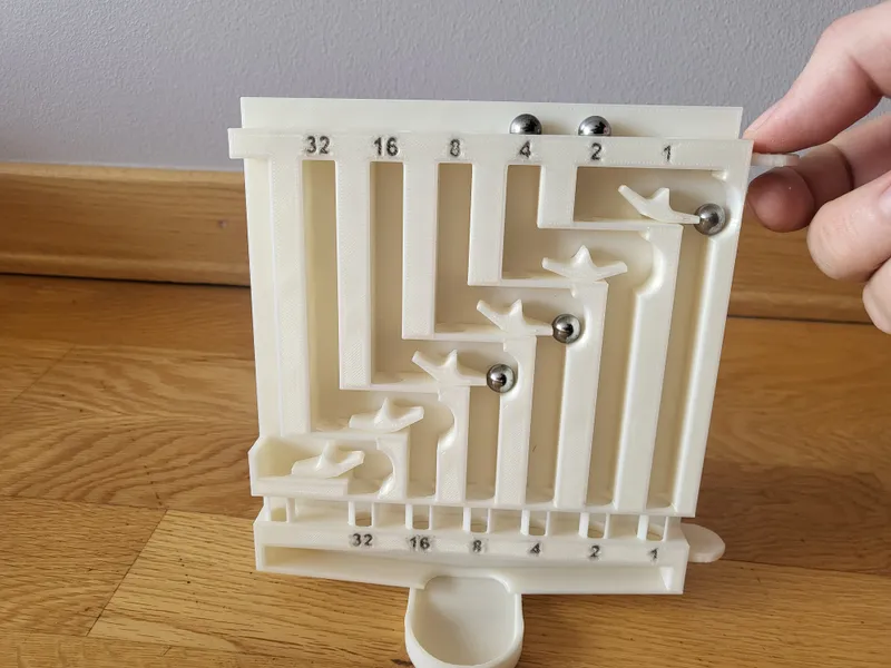
- Pull out top handle and let all balls fall down on levers.
- If you want to continue to add more numbers, just repeat steps 7. - 8.
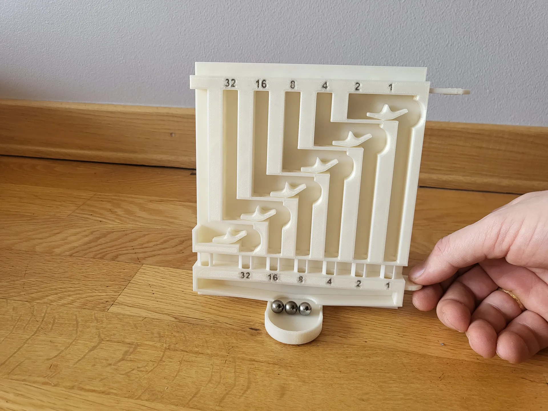
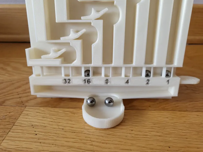
- Whenever you need a result - pull out bottom handle. bottom holes will close, all levers will flip back to the left and release all the balls, that are in the system.
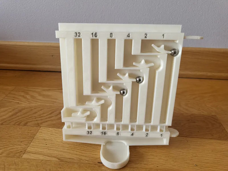
- On the bottom row is your result. (in our example it is 16, 2 and 1, which is 19)
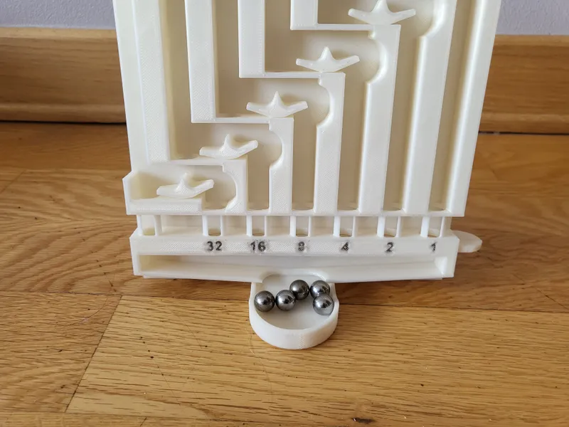
- Pull out and push back in bottom handle to reset result and release all the balls.
Here is original authors video with in depth explanation on how this machine works:
Tips for printing
- Layer thickness - 0.2 (This calculator is designed with 0.2 - 0.4mm tolerances. It is recommended to print with 0.2 layer thickness. It will also work with 0.1, but most likely there could be problems with something in between or grater thickness)
- Skirt - off (For Prusa Mini it is necessary to turn off skirt otherwise it will not fit. Larger printers can keep it )
- Brim - No
- Supports - No
- Material - PLA (I have not tested other materials. PETG may be to stringy and to easily fused together in tight places)
- Walls - 3 or more
- Infill - 10 - 15%
- Be sure to cut out any loose lines form bridging errors on the back side. They may get in the way of parts movement.
- Be careful when freeing levers and lever reset mechanism after printing. All parts should come free with little bit of force. If it is not, then try to cut around them with knife.
Only wall tolerances are set to 0.2 or 0.3mm. Bridging tolerances are 0.4 to 0.6 so there should not be problems with fusion together. - I applied bicycle chain lube on lever axles and other joints so they move a lot smoother
- I tried to print own balls, but they are to light to flip levers, so I use steel balls. You can easily find them on amazon
Known issues, that are not yet fixed in V1.0
- Balls sometimes bounce out of the calculator
- Levers are to light and from movement vibrations wobble themselves straight. They should always be to the left or to the right
- Sometimes lever joints print to tight and they get to much friction. This results in balls not being able to flip them.
Tags
Model origin
The author marked this model as their own original creation.


