RC Slow Flyer Plane Hybrid Foamboard

Description
PDFFoam Board hybrid RC plane designed to help teach my grandchildren how to fly (interpret that as strong but it won't bother me if I have to make multiple).
It has an under-cambered wing, so it is a slow flyer (which is also good for learning pilots). It is a pusher design so if they plant the nose, the motor might just survive.
Uses two sheets of Readi-Board foamboard (DTFB): one for the two wings, and the other for the stabilizers and fuselage. All of the ribs and fasteners are 3D printed.
The wing tips are especially shaped to hopefully reduce wing-tip stalls. In a rough foamboard method it is using the Prandtl 2 wing approach providing a negative vortex.
Instructions
It is worth noting that I am revamping all of the instructions. Please be patient.
Print out all of the parts (see the Printing section for instructions).
Wings
Use the attached drawing to get the correct dimensions of each wing.
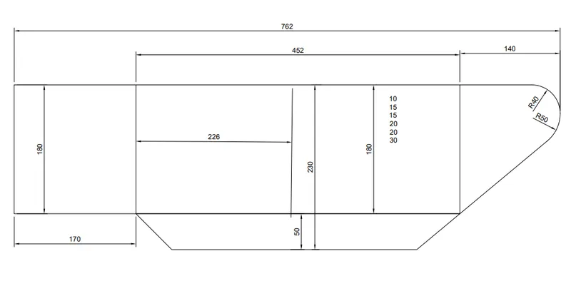
There is a template drawing to provide the shape of the wingtip. You will make the entire wing with one sheet of foamboard (20x30x3/16 inch, 508x760x5mm).
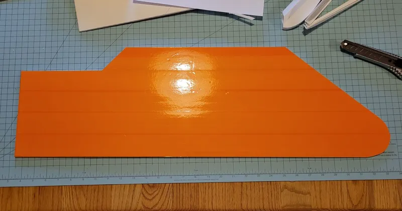
Cover one side with packing tape (tip: cover left/right wings with a different color to make it easier to identify orientation while in flight). Using the template and drawing cut the outside shape.
The foamboard parts use a methodology similar to “flitetest”.
Turn the wing so the taped side is facing down. Measure for the hinge of the aileron. “CAREFULLY” partially cut about halfway through the foamboard. Use an old gift-card to slice the rest of the foamboard without damaging the lower paper or plastic packing tape. Bend the aileron back 180 degrees.
45-degree bevel cut both edges to allow for free movement of the aileron.
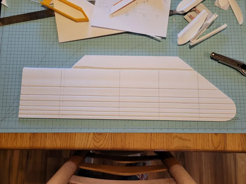
On the drawing there are 6 numbers near the leading edge (10, 15, 15, 20, 20, 30). Measure from the leading-edge lines with the provided spacings. Partial cut the lines (parallel to the leading edge), then use the old-gift card technique to break through the rest of the foam. Use a pencil to press the foamboard to provide a compressed “V”. Crease and fold the lines to create a smooth “arc/foil” shape.
Ribs and what not
Using CA glue, I attached a rib 140mm from the wingtip. Start at the leading edge and try your best to conform the foamboard to the rib.
Mount the boom pod at 140mm from the wing-root. Make sure that is perpendicular to the leading edge, otherwise the tail assembly will be misshapen.
Mount the Aileron Rib about 220mm from the boom pod.
And then mount an additional rib halfway between the aileron rib and the furthest rib.
Printing
Most of these parts were printed using Overture PETG
Most parts use 5% hatch infill, 2 top layers, 1 bottom layer, 1 wall (perimeter).
Print motor mount using PETG or better.
Wing Rib (two copies and two mirrored copies [4 total]): print on side with the top surface facing away from the bed.
Aileron Rib (two copies, one mirrored): print on their sides with the top surface facing away from the bed.
Boom Pod (two copies, one mirrored): Orient on its tail. use brim for better bed adhesion.
Stabilizer Mount (two copies, one mirrored): Orient on its tail. Use brim for better bed adhesion.
Stabilizer A Top: Orient on its tail. Use brim for better adhesion.
History
2023-11-09: Major rework to make most of the parts printable with PETG. Pretty much a redesign to make many parts work together better.
2023-11-02: upgraded Aileron Rib to have an embedded servo.
2023-10-25: Initial release
Tags
Model origin
The author marked this model as their own original creation.


