Yet another Can Dispenser (10x 500ml, 67x169mm cans)

Description
PDF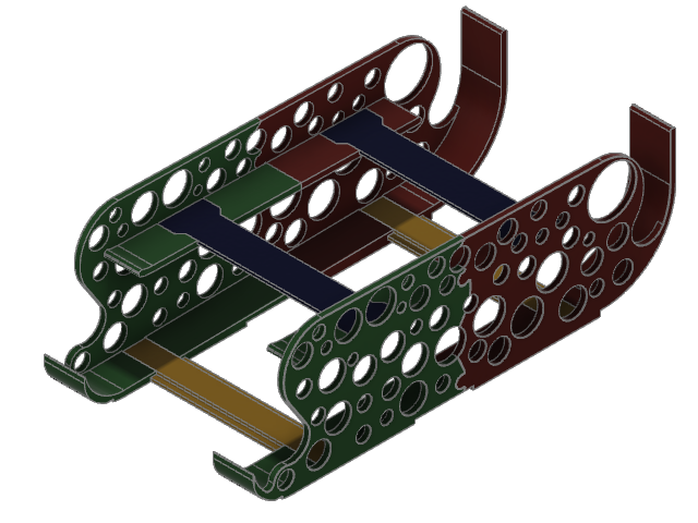 “Years ago" Inspired by all kind of clever solutions at the time, I designed a dispenser for 330ml cans which printed in only 4 pieces on my BIG 3D printer (~450mm x 450mm x450mm) which rests in piece ;-(
Luckily the local brewery decided to change to 500ml cans.
I had a look at lot of current designs but I could not find one for 500ml cans, that fitted my needs :-(
So, I decided to make a new design for my latest fridge, which could be printed on the Prusa I3 series.
This time I also tried to remove some of the issues of my old design.
- when filling the tray from the top, the tray slides, because of the speed of the cans rolling down the guides and bumping the rear catcher.
- the 1st can, when filled in from the top, gets too much speed and jumps out the lower tray front
- the tray bottom sits on the front, rear or center plastic trims of the glas-trays.
.. and the dispenser slides around.
I started by taking some measurements.
It turned out, that 4 out of 5 glas-trays in my fridge have different dimensions!!
The depth is different and or the front, rear plastic trims are different
and one tray has a center plastic ( this is a split glas-tray)!!
Not to mention different heights, of course.
So, this design only fits in a fridge (Samsung), with the following tray sizes:
Design depth: 365mm
Rear trim clearance: 65mm
Front trim clearance: 340mm
There is also a clearance for the split-tray plastic trim,
starting at 175mm from the rear, with a width of 50mm
This time I also changed:
- top and bottom guides are at only 0.8 degree slope, which seems to be OK.
- The front catcher is now high enough too catch even the fastest cans :-)
- There are cutouts at the floor of the dispenser for the plastic trims
- There are also some indents for silicone bumper feets
with max. 16mm diameter and more than 2mm height.
There are connectors and some guides for putting front & rear parts together.
They only slide together from one side!
So there should be no problem too align and glue the parts :-)
The bottom connectors are T-shaped and fit snugly into the side parts!
(I did not need to glue them)
The spacers/connectors can easily adjusted for shorter or taller tins, in Fusion360
The top spacer are inverted “T” shapes and also guided and do nicely fit into the desired spaces, but need to be glued.
All the wholes are randomly placed.
I just made sure that they don't create overhangs, which would require support!
I just thought that it looked better :-)
… and uses less material to print (I hoped)
Printing:
Just check the included 3mf files
NO supports needed.
Infill density and can be changed to almost anything.
Caveat:
Do not change the “layer height” of 0.2mm AND the “nozzle diameter” of 0.4mm
.. otherwise the connectors might not slice correctly!
I used grid infill and 2 perimeters
The ”skirt" is only 1 layer high
(I do not see the point, that the default skirt is 3 layers. Does anyone know?)
I even printed one “without” bottom and top layer using honeycomb infill - looks nice :-)
This also works, but one has to add some modifiers,
to make sure, that the “shoulders”(guides) and the side parts have a full layer for better adhesion!!
So your choice :-)
The Fusion 360 file is included and has parameters, one can play around with.
But almost every time, a parameter change will cause some errors along the timeline :-(
So, do NOT ask for design changes because it does not fit!
Except for the parameter of the “can height”, which should be given very precisely!
I added just a 1mm tolerance to the can at both sides!
It might be possible to adjust the length of the connectors in Prusa slicer( NOT tested)
Cheers
PS:
I incidentally uploaded a version, where the guides where “triangle” shaped.
Did also work!
… but not as good as the later version with “T” shaped guides.
I also noted that the floor connectors where about .2mm to wide
This should be the correct version now. (sorry for that)
The “T” guides, slice and print and work, much better :-)
NEW floor connectors - 0.2mm smaller in height & width.
( should fit easier)
… prints also very well in PLA
Tags
Model origin
The author marked this model as their own original creation.


