BambuLab P1S/P1P Modular Fan Ventilation
Description
PDFI will only describe what has canged.
Please go to the original models for their description:
For the Top Riser please follow the instructions here:
Print everything here besides the four frame parts.
https://www.printables.com/model/373694-bambulab-x1c-ventilation-with-without-led-mrw
For the Front Button follow the instructions here:
Do not print anything from here you'll only need the Button and Base parts I modified.
You'll need the electronic parts from here:
- The Switch
- The 5V LED Strip
https://www.printables.com/model/494647-bambulab-p1pp1s-usb-led
What you need
Printed Parts:
For the Frame:
- 1x FrontLeft-Rised
- 1x FrontRight-Rised
- 1x RearLeft-Rised
- 1x RearRight-Rised
For fan Module:
For each fan Module you need 1x SideCover and 1x FanCover
SideCover-Type1 fits for rear left and front right
SideCover-Type2 fits for rear right and front left
depending on the thickness of your fan you'll either need the FanCover-10mm or FanCover-20mm.
For the Front Button:
- Button
- Base
For the Buck Converter Case:
- Buck_Board_Box_Open_Ends_Base
- Buck_Board_Box_Open_Ends_Lid
Parts to buy:
Please refer to the links above I only list additions or changes here
Changes:
For The Frame:
- Wire 3mm diameter max. (inclusive insulation)
Additions:
For the Frame:
- 4x calbe clips (for easier installation and removal of the top riser)
- 1x LM2596 Buck converter
For one Fan Module:
- 2x 3-Pin 40mm fans either 20mm or 10mm thick
- 4x 5x3mm magnets
- 8x M3x3mm threaded inserts
- Wire 3mm diameter max. (inclusive insulation)
- 1x 3-Pin Fan Y-Splitter or 2x 3-Pin Fan male connector
For a 20mm thick fan:
- 4x M3x20mm
- 4x M3x25mm
For a 10mm thick fan:
- 4x M3x10mm
- 4x M3x15mm
For the Side Cover Holder:
- 6x M3x30mm
- 16x 5x3mm magnets
Assembly:
Power off your printer and disconnect the power cord!
Take off the backplate.
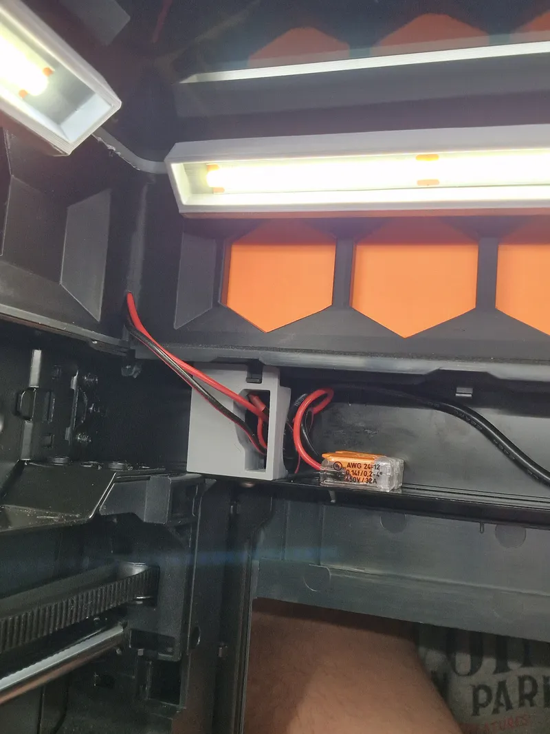
Run a wire from the printer PSU to your buck converter and adjust it to 12V output.
Take the 12V wire an run in up the printer (rear left)
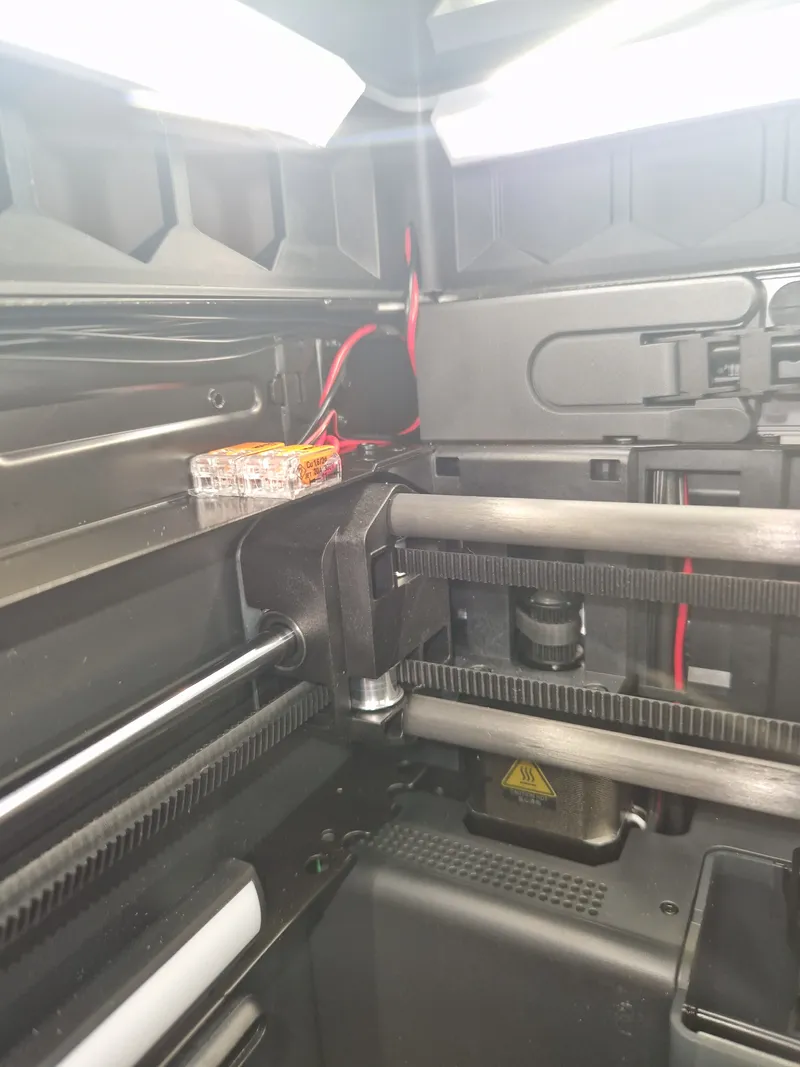
Assemble the four frame pieces. Do not insert the top magnets yet.
For the assembly and light please refer to the original model.
All the fans have to be connected in parallel.
Run the wire from the rear left corner (where the hole is) all the way around.
It worked best for me by opening little gaps in the inulation with a wire stripper and solder the wires to the magnets to it.
Wire the magnets as follows on both sides: (the longer side is positive)
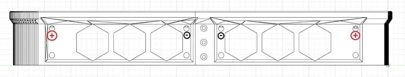
Since magnets loose their strength when heated I do not recommend soldering the wire to the magnets.
Just remove some insulation from the wire and press the magnets onto it. Like this:
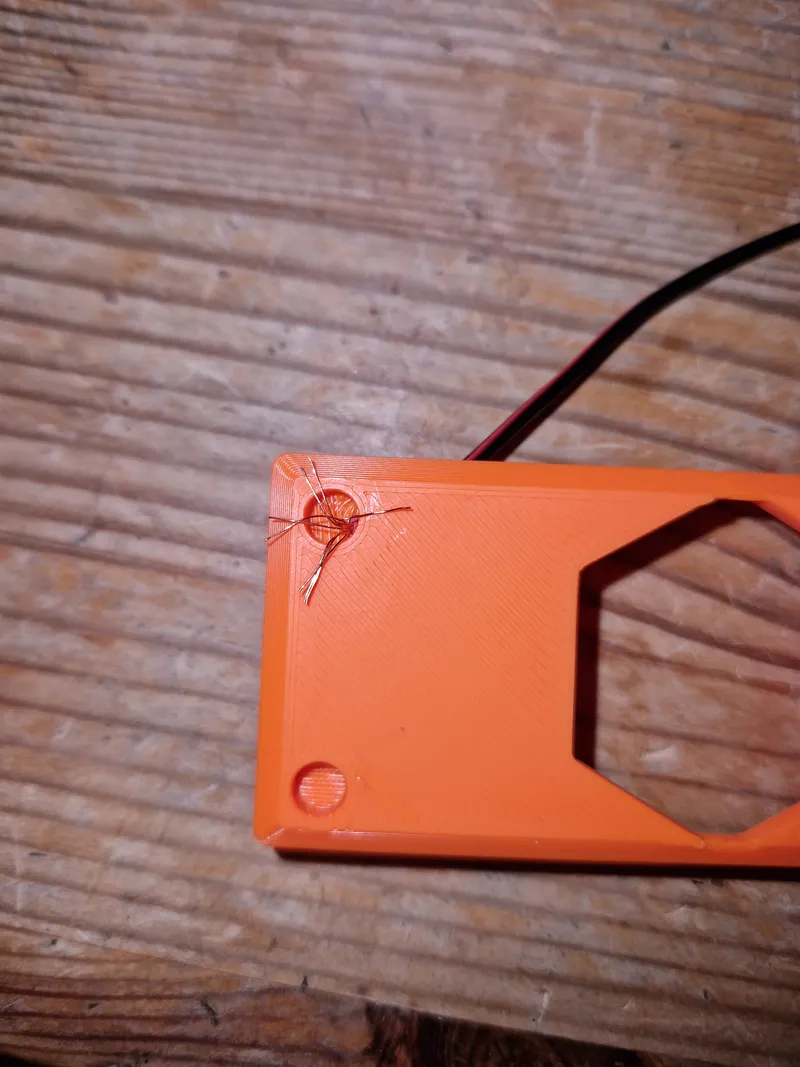
Afterwards you can remove the excess wire.
Assembly of the Fan module:
Connect the magnets with a wire using the same process as shown above. (the longer side is positive)
Put in the 8 threaded inserts.
Screw the fans on the Fan module with the shorter screws.
Connect the two fans to the Y-Splitter cut off the female plug and solder it to the wires coming from the magnets.
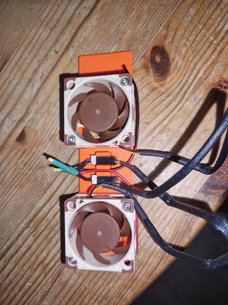
Do some cable management and youll be able to fit the FanCover onto it. Use the 4 longer screws to screw it together.
Assembly of the button:
Please refer to the link above for the installation of the button.
There is a hole on the bottom where you can also insert a M3 threaded insert to mount it to the frame.
You can use the hole in the FrontRight Frame piece to run the wire up to the cable canal.
Assembly of the Side Cover Holder:
Put the magnets into the holes.
Screw the Side Cover Holder and the Side Cover Spacer to the side of your top riser using M3x30mm screws.
Tags
Model origin
The author remixed this model.


Differences of the remix compared to the original
Top Riser:
- widened the cable canal in the frame to fit more cables
- added holes in RearLeft and FrontRight to get the cables to the top
- added holes from the top magnets to the cabel canal
- removed the RearRight calbe exit
Button:
- changed the size of the button base to fit into the P1S
- changed the button size
Buc Converter Box:
- cut off 1mm from the base making it lower