Desktop fan V02

Description
PDFOn the pictures a fan grid with honeycombs is to be seen, this file broke me unfortunately. I still submit this when newly created.
Update 01: there are now a few more fan grills to discover.
“Target” “Tornado” “Spiderweb” “Pyramid” “Honeycomb”
Instructions for tiltable desktop fan
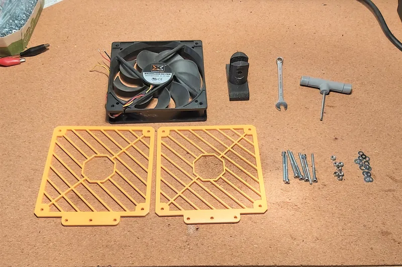
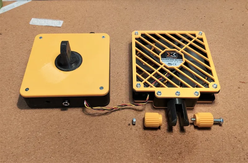
Print the following parts 2x:
- fan grid
- locking knob for joint (use with M5 screw and M5 nut)
The remaining parts have to be printed 1x:
- lower part of the box (the one with lots of holes)
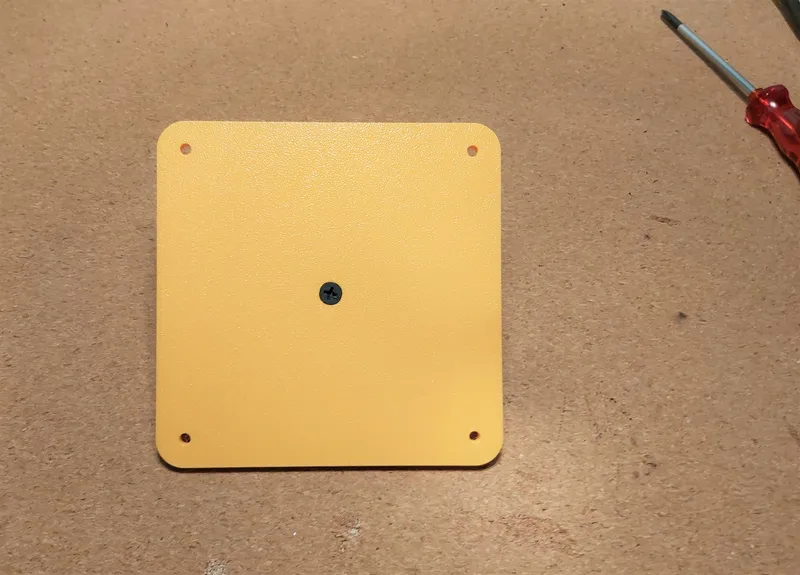
- box lid (also has lots of holes)
- joint for the lower part
- joint for the upper part
The following parts are also needed:
- 1x quiet PC fan, 12V, 120x120x25 mm, 1200-1500 RPM (take e.g. one from your old PC)
- 1x circuit speed controller with rotary potentiometer and adjustment knob
https://www.ebay.de/itm/404369048935
- 1x voltmeter
https://www.ebay.de/itm/145262180473?var=444446073443
- 1x on/off switch
https://www.ebay.de/itm/184271526253?var=692189446478
- 1x plug-in power supply 12V, 0,5A, with hollow plug DC 5,5x2,1 mm (local hardware store)
- 1x female socket for hollow plug DC 5,5x2,1 mm
https://www.ebay.de/itm/165845903618?var=465347540525
- 4x self-adhesive rubber feet (local hardware store)
- approx. 1m cable red/black (local hardware store or electronic store)
Varying screws are also needed:
- 1x screw M5x40
- 1x nut M5
- 1x Spax screw about 3x15
- 4x countersunk screw M3x20
- 4x press-in nut M3, about 5mm high
- 2x Allen screw M2,5x10
- 2x nut M2,5
- 7x Allen screw M3x35
- 7x nut M3
- optional 14 washers M3
Instead of the Allen screws, hexagonal screws or pan-head screws can of course also be used.
I bought all screws, nuts, washers etc. at the local hardware store or online here: https://www.schraubenkasten.de/
Required tools:
- Phillips screwdriver
- Allen key for M3 and M2.5 screws
- ring or open-end wrench size 5.5
- small pliers for M2.5 nuts or a suitable ring/open-end wrench
- soldering iron, solder, solder flux
- wire stripper
- superglue
- insulating adhesive tape
- heat shrink tubing
Assembly of the parts
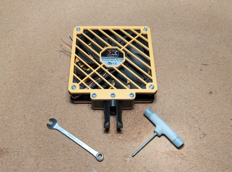
Step 1: Screw both parts of the fan grid to one side of the PC fan each. For this use 4 Allen screws M3x35 and 4 M3 nuts, optionally with washers.
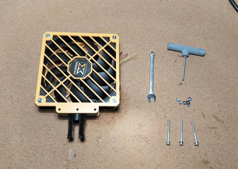
Step 2: Screw the upper part of the joint to the bottom of the fan grid using 3 M3x35 Allen screws and 3 M3 nuts, optionally with washers.

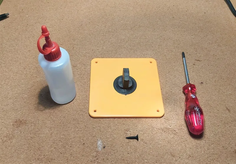
Step 3: Align the lower part of the joint with the small lug on the lid (must fit into the small bulge on top of the lid) and glue it into the flat circle with some superglue. Additionally, from the bottom, if desired, screw the joint bottom part into the centre of the lid with the 3x15 Spax screw.
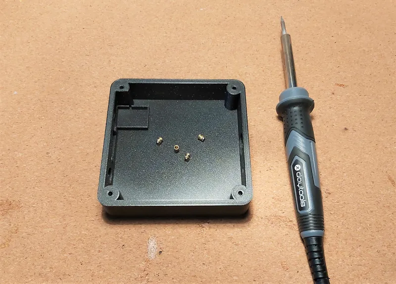
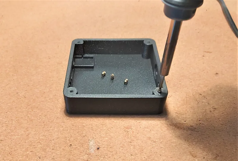
Step 4: Melt the press-in nuts into the lower part of the housing using a soldering iron. Make sure that the press-in nuts are absolutely vertical. Remove any protruding edges with a sharp knife. Caution: The insert nuts may still be very hot!
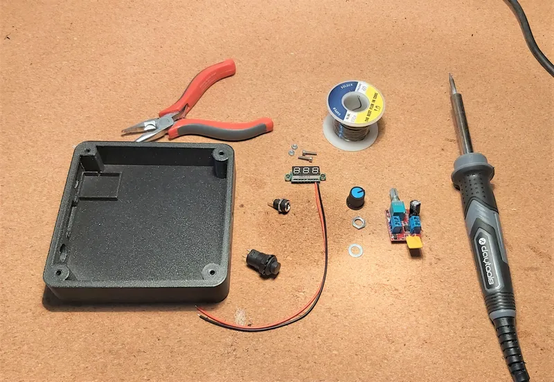
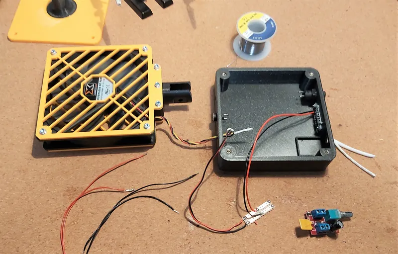
Step 5: Solder electronic parts, switch, and socket, see attached wiring diagram as PDF or JPEG for wiring of components. It is recommended to insulate all exposed bare cables and contacts with heat shrink tubing.
Important: please pay attention to the polarity at the socket, the speed controller circuit, the voltmeter, and the PC fan.
The cable of the PC fan can be inserted through one of the holes on the back side. If you have soldered the hollow plug socket and the on/off switch for testing, you may have to desolder them again for installation. I recommend leading the cables through the corresponding holes beforehand, so that these 2 components can be installed directly without desoldering.
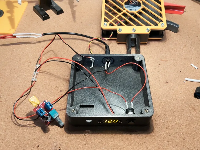
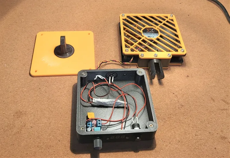
Step 6: If everything is soldered and tested correctly, all electronic elements can now be installed in the housing. See photo for placement.
Step 7: Now screw the cover onto the housing using the 4 M3x20 countersunk screws but be careful not to overtighten them.
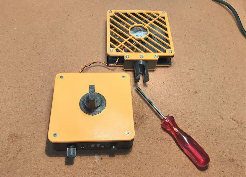
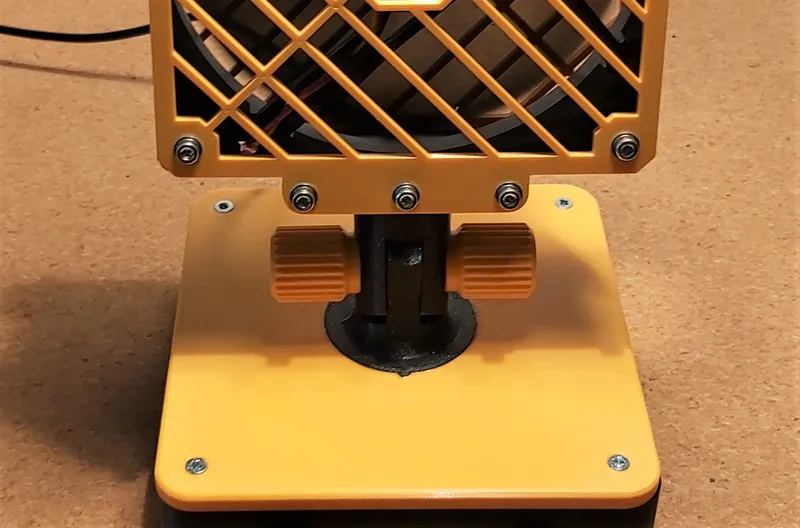
Step 8: Wedding! Connect the bottom part with the top part: screw together with the M5x40 screw of the M5 nut and the 2 printed knobs. Now find the right angle and tighten the adjustment knobs.
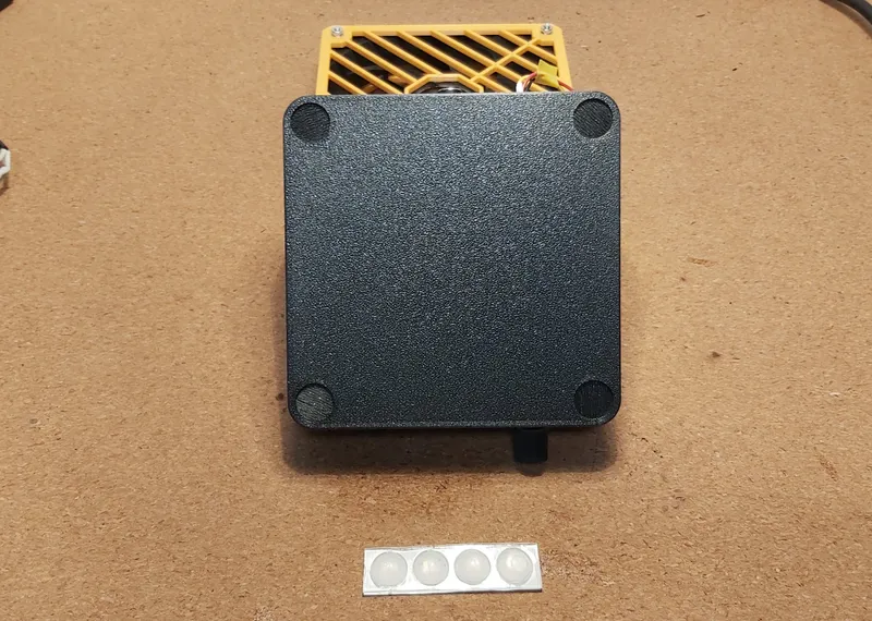
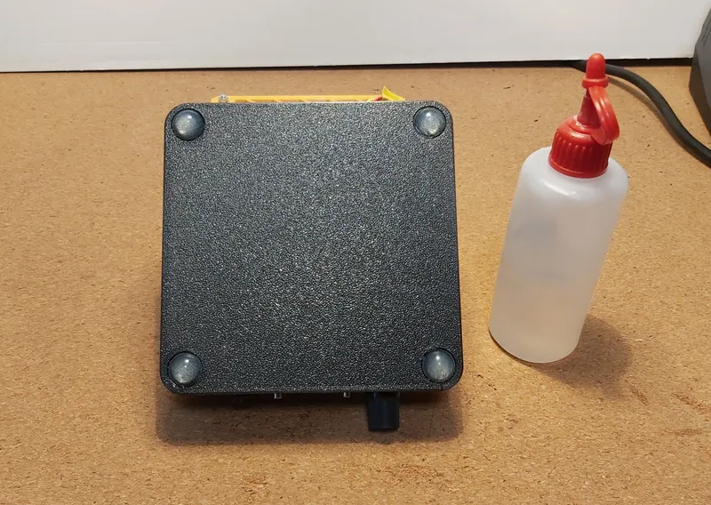
Step 9: Glue self-adhesive rubber feet to the underside in the recesses. I recommend using a drop of superglue as experience has shown that the rubber feet can quickly come off.
Step 10: Plug the power supply into the socket and insert the hollow plug into the socket at the back of the fan. Switch it on at the front right and adjust the speed with the potentiometer knob.
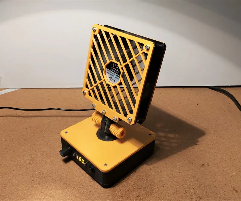
Enjoy the cool air!
Tags
Model origin
The author marked this model as their own original creation.


