Open Timer Platform
Description
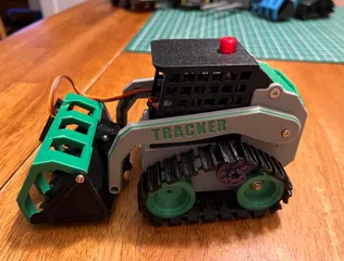
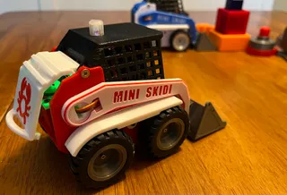
PDFThis timer was originally designed for use with remote control Skid Steer models to allow them to start/stop a timer as they completed challenge events. However, the components are modular. You can add a single or double pushbutton. The code is simple and can be easily customized by the user for a multitude of purposes. The heart of the unit is a simple Arduino Nano v3 (clone) and a 1.3" OLED display. Each are available for under $5 from AliExpress or other vendors.
The pushbutton design used was from megardi @ https://www.instructables.com/Mostly-3D-Printed-Push-Button and modified slightly for use with this timer. The unique feature of this pushbutton is that it uses magnets for “springs” and a reed switch to open/close contacts. After testing, it was found that no debounce software was necessary for the reed switch.
The 16MHz Nano provides a 1Hz timebase for the basic timer. It is not as precise as a stopwatch. But for casual competition, +/- one second in 5 minutes is suitable.
Hardware:
- Arduino Nano v3 (clone)
- 1.3" OLED with SH1106 controller
- Reed switch: 3x14mm square plastic case with 10-25AT pull-in
- 4x2 pin JST or Dupont connectors with wires
- 1x4 pin female-female Dupont connector
- 1 x 9v battery
- 1 x KCD11 plastic power switch (rocker)
- 5mm & 8mm flat Head M3 screws
- 2Mx6 screws for OLED
- 10 x 6x3mm rare earth magnets, round. Most on AliExpress are 2.6mm thick and fine.
- 5v Active Buzzer 16R fit 12085 (12x8.5mm) round.
- roughly 53x57mm PCB Copper one-side, copper around each hole.
Printing:
0.2 layer height for all parts except the pushbutton bits that move
3 perimeters - 3 layers top/bottom
PLA or PETG. I used PLA
Assemble:
For the button, PBbody, and cap, I recommend 0.1mm layer height so you get a smoother finish.
You must orient the magnets with the same polarity on the bottom of the case. And then ensure that all 3 of the button magnets repel from those in the case. The middle magnet hole in the button is deeper than 3mm. Only put the magnet 3mm deep so it is flush with the surface. If you find it triggers too easily, then push it slightly deeper in the pocket to reduce sensitivity. The reed switch is tricky. If the magnet is too close to the reed switch, you may only need to depress the plunger a bit to trigger the reed switch closed, but when you release the switch, it may not release. (something called hysteresis) Hence a new press is not recognized because it is waiting for the release. In this case, you might need to push the middle magnet slightly further into its pocket. This will force you to press the plunger further to engage, but it will disengage when you release. This is the tricky part of the calibration. Also, I've had one reed switch fail “closed” on me. Replacing the reed switch solved the issue, so if you glue the reed switch down, just use a drop.
Your OLED may have slightly different mounting geometry. I've found there is no standard and so I am developing a different mount that will handle slight differences in the mounting hole dimensions.
There WILL be sanding required on the parts of the switch above to get a good fit and smooth operation. I recommend 1000 grid sandpaper. Patience here is a virtue.
Wire components as shown in schematic and physically as shown in pictures above.
Code is included in the ZIP file and created in C++ using the Arduino IDE v2x.
Step files available on request.
Tags
Model origin
The author marked this model as their own original creation.


