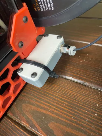
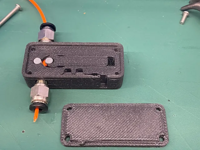
Filament width sensor (hall sensors)
Makes
Comments
@agDesign_327524 It does not have separate firmware. It is designed to work with the Klipper 3D printer firmware. You can find instructions in the link provided in the description, which directs you to a page (original design) with guidelines and details on how to configure it.
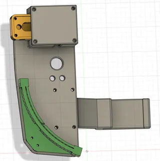
Made one and combined it with the runout/jam detection sensor:
https://www.printables.com/model/1084045-mounting-plate-for-combined-tangle-runout-detectio
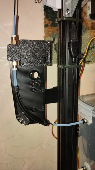
Printed fine. The sensors are so hard to install. Soldering them is almost impossible. I ended up wasting 2 sensors on my first attempt before I realised using cable was much easier. I also snapped open a case I printed so I could solder them in place, before then inserting them into the final case. Put simply, I am glad I do not need to install those sensors again. I haven't tested it yet for reliability but the filament fits well inside and it seems promising.
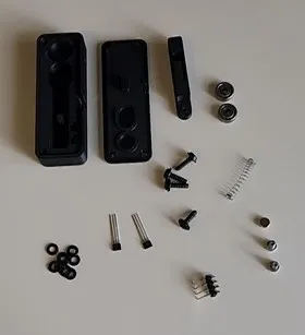
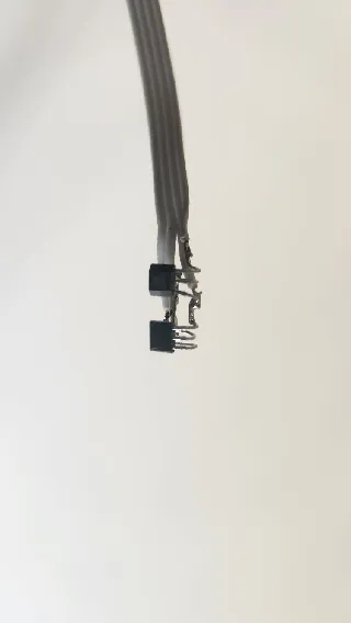

I'm on a bit of a filament sensor binge at the moment. So far the V3 design seems to have the least amount of resistance to the filament, which isn't really what I expected. Let's see how it fares in actual use...

@pol_23284 please post the graphs or the data about the measurements!
Tolerances were fine for me. Just not enough space for cables. Also I extended two of the holes, so it can be mounted to a 20x20 rail
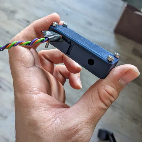
@Neelix are the measurements reliable? I did the one with bearings and they are not
@Pfsen_43597 not yet. I mean, I have nothing to confirm the diameters, but a had some problems with not correct soldered cables, which greatly affected the readings
I printed v1 and wow you went really tight with tolerances... but I managed.
However, bending properly and preparing the connections to the chips is quite difficult. Please cut your main.stl like shown so that people can print it and use that to bend/solder connections. I would upload it but I can only attach pictures.

@PequiVoo_1424530 after that I bought reliable (Austrian, I think) bearings which were perfect (5 euro the pair) and by measuring the filament I got noise of about 1 micron and no periodicity, meaning that the values don't oscillate with the period of the circumference.
The poor bearings were showing readings which were going up and down at every turn of the bearing.
So overall, if you buy good bearings, the solution works. Pins might be just easier though, assuming no abrasive filaments are used. Still they will wear out making the correction less accurate over time.
Another solution is to get plain steel pins, make them red hot under a flame, throw them in water and then install them: once hardened this way, only really abrasive filaments would wear them out.
@Pfsen_43597 Primarily, I ordered precision bearings, too. But switched to bearing pins, which are hardened by design. So, wear and tear is not very likely.
As I think, that the InFiDEL from T. Sanladerer has some advantages due to the lever design ->friction is minimal, maybe I try this too, when I am not satisfied with this design here.
Can you please provide a link or more specific part number for the v3 bearings? Thanks!
@JaradO_29041 I bought rollers at a local bearings hardware store.
You can try searching from Aliexpress or eBay with cylindrical roller bearings or cylindrical roller bearings pins or needle bearing pins.
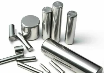
@Janar_102020 how does this rollers rotate in printed part? Or should they just allow filament to slide?
What's the advantage over the original design?


