Raspberry PI 4 Case

Description
PDFAll of the pieces are in their optimal orientation, so it would be better if you did not change this.
The G-codes are for print times only, please slice your own. (It's for your own good!)
I have included a .3mf file for support reference.
You will need:
A fan:
~ 47.6 mm X ~ 47.6 mm x ~ 10 mm
(not perfectly sure on the dimensions, so feel free to measure the cutout.)
8 6-32 screws:
head dai. : ~ 6.4 mm
length: ~ 16.5 mm
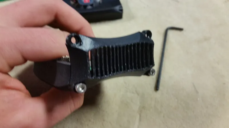
1 mm dai. optical fiber:
length: ~ 83.9 mm (3.3 in)
ASSEMBLY:
Step 1:
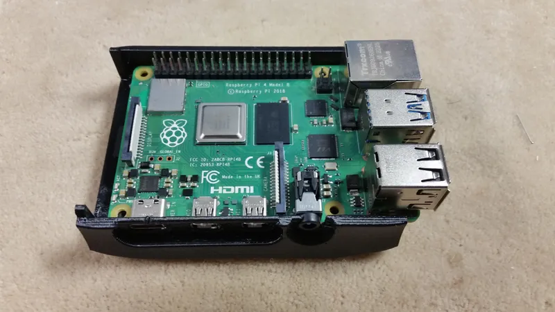
Put your PI in the bottom. Use whatever screws you can find to hold that fits and threads into the plastic holes.
Step 2:
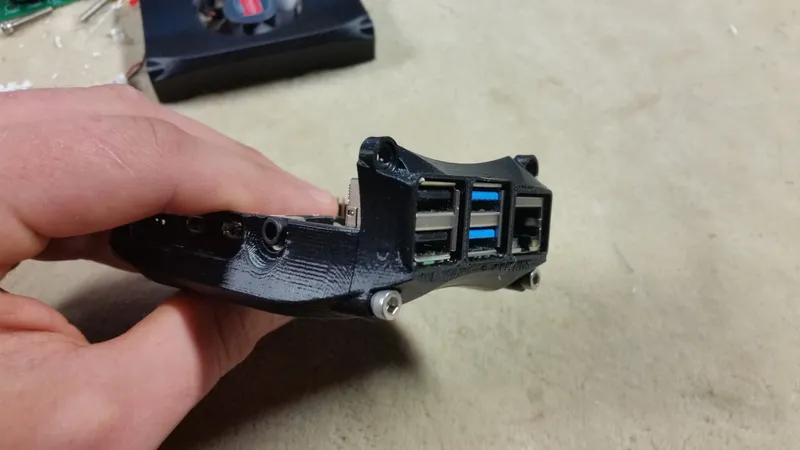
Put the front on. use two 6-32 screws, there are no nuts. The case is designed so that the screws thread into the plastic.
Step 3:
Do the same on the back.
Step 4:
Put a fan (if you want one) and the optical fiber (if you want that either) in the top.
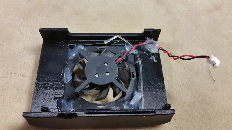
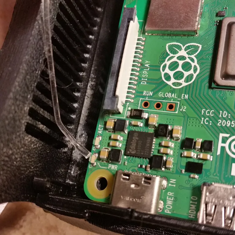
Step 5:
Use Hot-Glue or something similar to secure the other end of the optical fiber cable near the power indicator light on the back of the PI (Mine isn't hot-glued because the glue got removed)
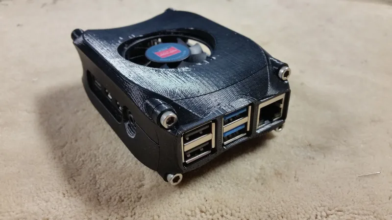
Step # the last one:
Put the top on the rest of the assembly and screw it in with 4 more 6-32 screws. Again, NO NUTS.
TA DAAA!!!! You can now hit it with a hammer.
Tags
Model origin
The author marked this model as their own original creation.