DLD Filament Buffer for MMU

Description
PDFThis is a “ground-up” model inspired by "The Wedge RMU Mk3" Buffer. https://filamentbuffer.co.uk/
I did a lot of research on buffer systems and found the approach taken by their design was almost exactly the form factor I wanted. I didn't want to pay for stl's that I couldn't natively and readily modify in SolidWorks. So I made my own version.
Many neat attributes in this design:
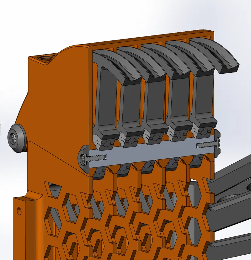
- Lofted filament feed pathways in and out for near frictionless overlap as the filament enters and exits the wheels
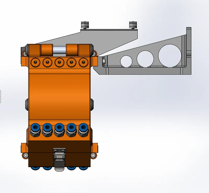
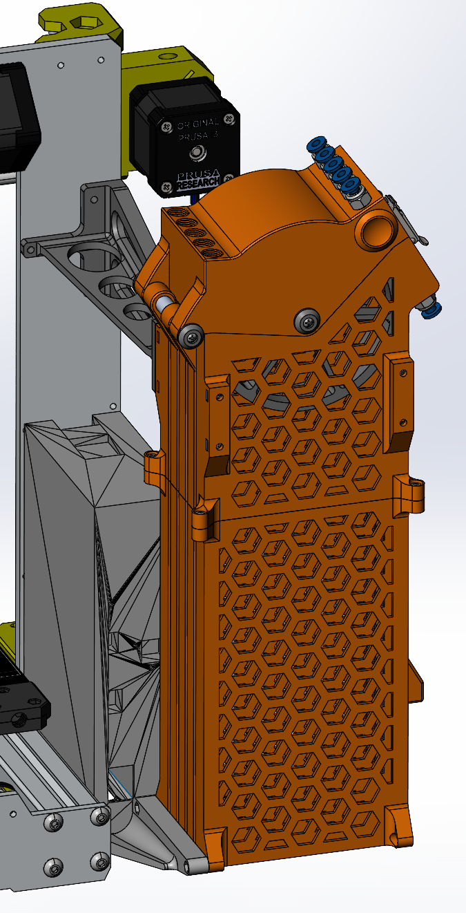
- used a metal draw latch from McMaster-Carr for added durability https://www.mcmaster.com/1794A51/
- This Draw Latch is also on Alibaba https://www.alibaba.com/product-detail/TS-163-3-Cash-Dispensers-Medical_60399012262.html?spm=a2700
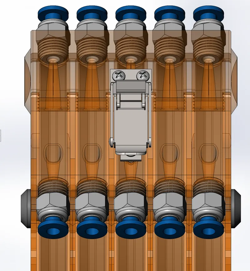
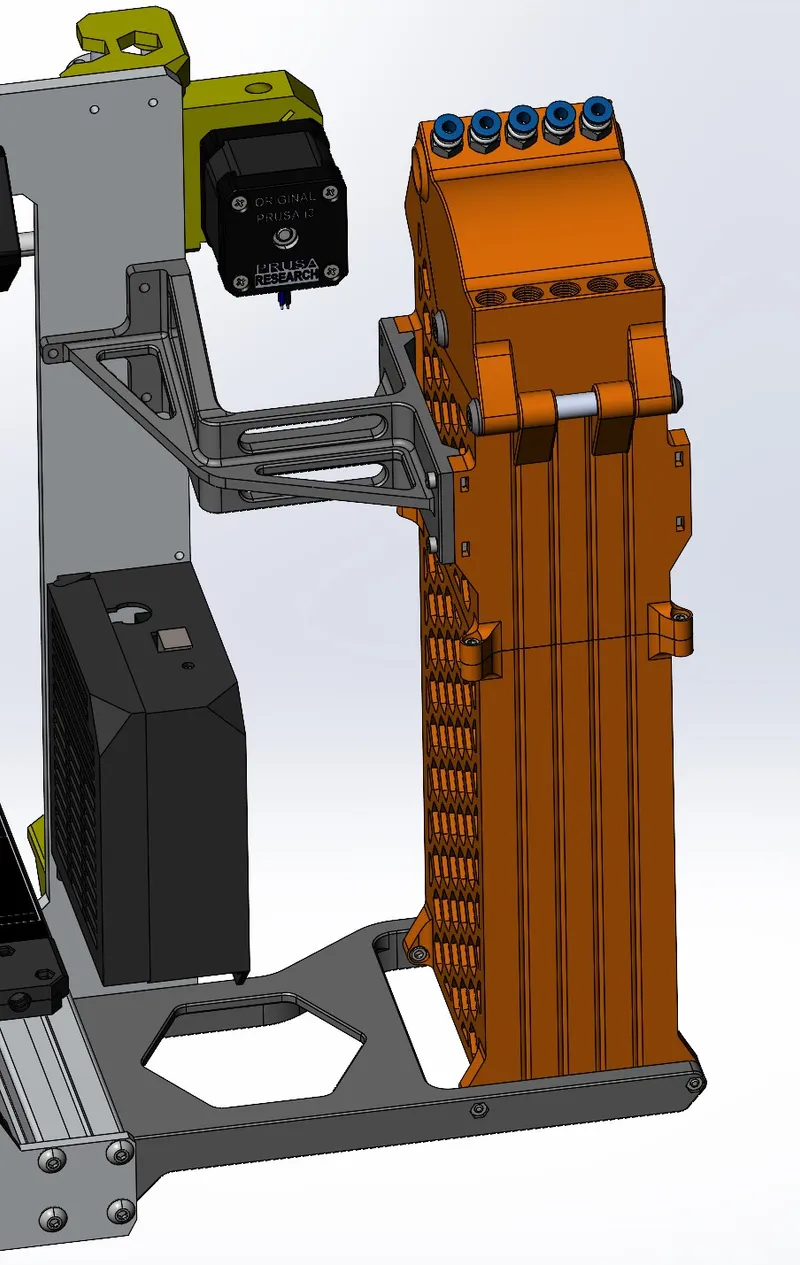
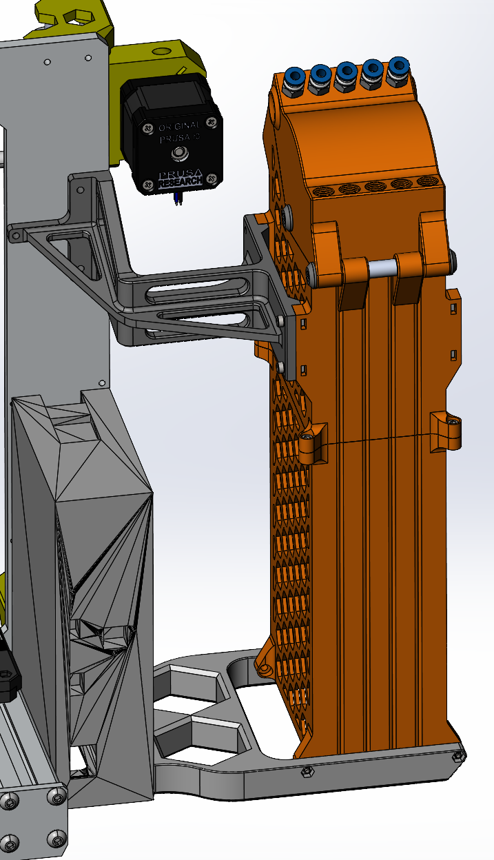
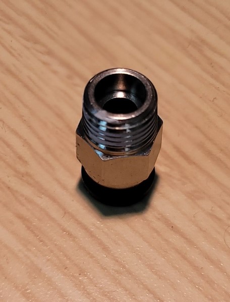
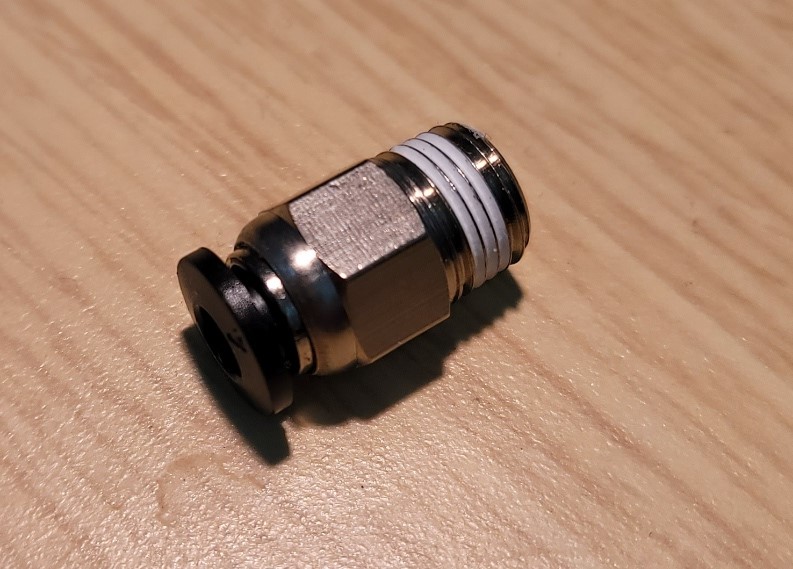
- used the common PC4-M10 pneumatic couplings. I found a 20 pack on amazon. The tube ends stop at the end of the coupling since the lofted clearance holes were added. Female threads were added to the models to accommodate.
- Mounting provisions accessible from all sides for flexibility in custom mounting bracket solutions
- finger-pick button provisions added to cap sides for a little grip when opening
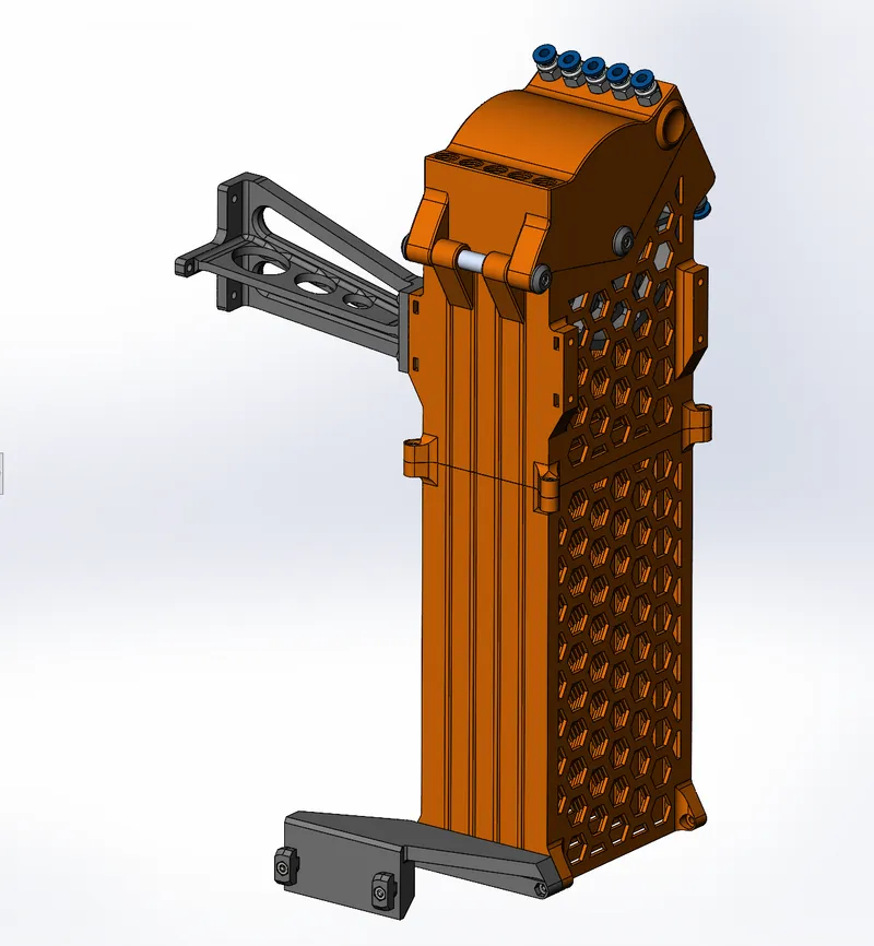
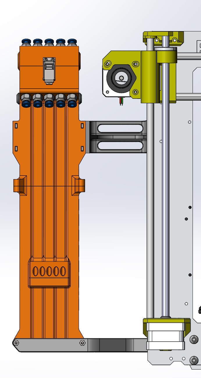
- Upper mounting bracket has a center hole large enough for a USB cable to pass through and connect to main board (MK3 ). Holes available for the MMU Cable as well.
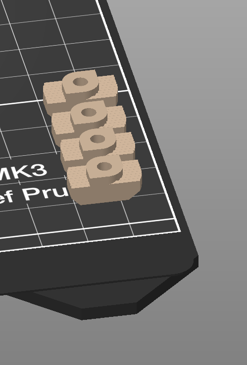
- all parts are 3d printable, including the bearing shafts and t-slot nuts.
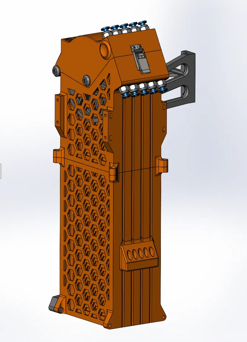
- Sides are ribbed vertically, which aside from aesthetics, seem to aid in the printing by reducing a bit of infill time.
- Thread forming screws were used on the bearing shaft ends and draw latch
- Bearing shaft ends https://www.mcmaster.com/99461A825/
- Metal Draw Latch https://www.mcmaster.com/99461A173/
- Square M3x.5 nuts are used for the upper mounting bracket and, depending on the manufacturing tolerance, will lightly friction fit into the slots.
- If your using the up-feed tube fittings on the side, I've added a tube management feature for routing
- I believe this is slightly narrower and the width is larger to allow for increased wheel diameter and bend radius of the filament. I found in an earlier iteration that some PLA material would break under strain
- Wheels are V-Shaped for some additional filament guidance/clearance
There are 2 different buffer caps. one is a single row of fittings and the other is dual for setups that mount the spools above the printer. The .step assembly contains the dual version.
A note on mounting bracket fasteners, they are the same for MK3 and MK4 for attachment to the buffer, however, I cannot confirm the MK4 Top Mounting Bracket fastener lengths needed to attach to the MK4 frame at this time. you may need 3 of the 12mm length. Perhaps someone can comment with the length needed.
Materials:
Fasteners:
- (4) #3 x 3/8" thread forming Phillips head screw
- (4) #2 x ¼" thread forming Phillips head screw
- (4) M3x0.5 x 10 mm socket head cap screw
- NOTE: will need 3 additional for mounting upper bracket to printer frame
- https://www.mcmaster.com/91292A113/
- (4) M3x0.5 x 12 mm socket head cap screw
- (2) M3x0.5 x 14 mm socket head cap screw
- (2) M3x0.5 mm square nut
- NOTE: design has provisions for 8 nuts, only 2 are needed for the provided upper mounting bracket design
- https://www.mcmaster.com/97258A101/
- (8) M3x0.5 mm hex nut
Bearings:
- (5) 608-2Z shielded ball bearing
- https://www.mcmaster.com/5972K501/
- NOTE: search for bearings that have a low rotation resistance, some of the bearings I found were packed with thicker/stiffer grease
Fittings:
- (10) the common PC4-M10 pneumatic couplings, I found packs of 10 and 20 on amazon
Draw Latch:
- (1) Tight-Hold Draw Latch
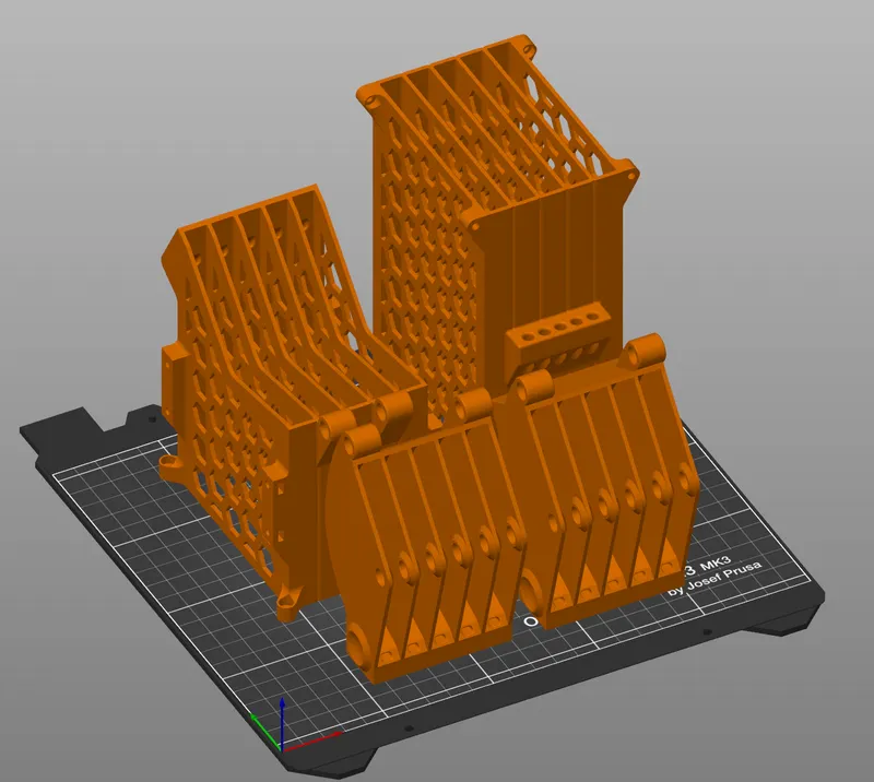
Printing Notes:
I printed all body and cap parts in PLA, All other parts PETG. I found the body parts containing the hex holes were a challenge in PETG due to bridging issues. I used default printing profiles in Prusaslicer. I also added a 5mm brim to all vertical body segments for adhesion during print.
I printed the bearing shafts vertically in close proximity to each other with a large brim for support. the shaft .step model is sized at 8.1mm to compensate for printing undersized, I then lightly sanded them for a great slip fit.
These are the orientations for the caps that worked the best.
I used .4mm Nozzle with .2mm layer height. 3 perimeters with 5 top and bottom layers on all parts. 3-4 perimeters should be used for the holes that take thread forming screws.
supports only needed for the T-slot Nuts and Top Buffer mounting brackets (both MK3 and MK4 versions)
Update: 2/15/24 - It was discovered that the “S” model printers have larger wi-fi modules and NFC readers, requiring different mounting bracket designs. I'm planning on adding these in the future.
File Names:
- MK3 Buffer Top Bracket - 90 degree side mount
- MK3 Buffer Bottom Bracket - 90 degree side mount
- MK4 Buffer Top Bracket - 90 degree side mount
- MK4 Buffer Bottom Bracket - 90 degree side mount
90° MK4 Mounting Brackets
MK3 and MK4 Rear Mount Brackets
File Names:
- MK3 Buffer Top Bracket - Rear Mount
- MK3 Buffer Bottom Bracket - Rear Mount
- MK4 Buffer Top Bracket - Rear Mount
- MK4 Buffer Bottom Bracket - Rear Mount
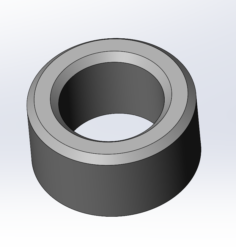
PC4-M10 PTFE Tube Collar
New Part added for use with the PC4-M10 Pneumatic Couplings pictured in the photos. It was discovered that this fitting does not fully support the PTFE tube end, allowing misalignment between the tube hole and the hole in the printed parts. If the PTFE tube is routed with tight radii into the fitting, this can cause filament to be pinched slightly, resulting in a high friction point. If using this fitting, print the collar and place it in the counterbore to provide proper tube alignment.
I've attached this in .step and .stl, It's modeled slightly oversized in ID and OD so that it printed dimensionally correct for me. But scale as needed.
Tags
Model origin
The author marked this model as their own original creation.


