Automated Heating System for Original Enclosure

Description
PDFUPDATE: V1.5 OF THE SOFTWARE IS OUT NOW (MAY '24)
(Also available on GitHub now!)
Fully automated heating system for the Original Prusa Enclosure
What's this and what does it do?
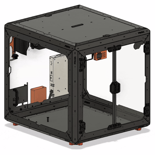
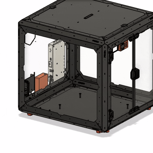
This is an automated heating system for the Original Prusa Enclosure.
The idea is to get the enclosure to the temperatures needed for good quality prints (40-45°C) with technical materials like PA11 / PC / ABS / ASA faster. Especially in the cold months, my printer alone isn't able to reach these temperatures, especially not in a reasonable amount of time.
The system consists of a 200W heater with a fan, a display with buttons to set a target temperature and to control the system, an electronics-box, an external powersupply and a “flap” moved by a servo to be able to remove heat from the enclosure.
All parts are mounted in or on the Original Enclosure.
The flap can be opened and closed - while open, the fan can blow air out of the enclosure to reduce the temperature inside. When it's closed it functions as a curved wall to redirect the airflow in the center of the enclosure.
Total cost is less than 100€ to build, which can be done in a few hours.
How does it work?
There are two main operating modes: Heating and cooling.
While in heating mode, the servo closes the flap and the heater and fan turn on. The air gets heated and evenly circulated in the enclosure.
When cooling mode is used, the servo opens the flap, the fan turns on but the heater stays off - that way the warm air inside the enclosure gets pushed outside the enclosure so it can stay near room temperature.
There are two more modes (fan and idle), more details are below.
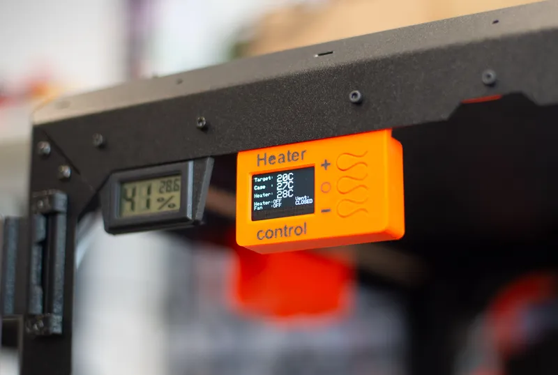
To control the system, there is a display unit with three buttons (+, - and o) placed in the top left corner of the enclosure. The display shows the target temperature, which can be changed with the + and - buttons, the temperature of a probe inside the enclosure and the temperature of the air coming out of the heater. The latter is used to turn off the heater if it should get so hot that the flap could melt.
Please note that this system cannot cool below room temperature, it's just able to remove heat from the enclosure by replacing it with room-temperature air.
Electronics & other parts
The electronics are kept as basic as possible.
Parts-list, including some example links:
- Arduino Nano (link DE, US)
- 1.3" monochrome 128x64 OLED-Display (SH1106) (link DE, US)
- 2x 10A-Relay module (link DE, US)
- 150W/200W heater+fan combo (I used 150W) (link DE, US)
- 2x DS18B20 temperature probe (link DE, US)
- 3V3 ⇔ 5V Level converter (link DE, US)
- 3x Tactile Button 6x6x7mm
- 3x 47k Resistor
- 1x 4k7 Resistor
- 3x 0.1uF capacitor
- Powersupply: You need 200W at 24V.
- The following ones are not recommendations but just to give you some ideas of which could work - you need to check which ones are legal to use in your country
- MeanWell RSP-200-24
- MeanWell LRS-200-24
- The following ones are not recommendations but just to give you some ideas of which could work - you need to check which ones are legal to use in your country
- LM2596S StepDown Module (link DE, US)
- SG-90 type servo (link DE, US)
- cabling for 8A
- signal cabling
Other parts:
- Cable-sleeving (link)
- M3x12 screws
- M3x16 screws
- M4x10 screws (PSU-Mount)
- M4x20 screws (flap)
Here's a block-diagram of the electronics:
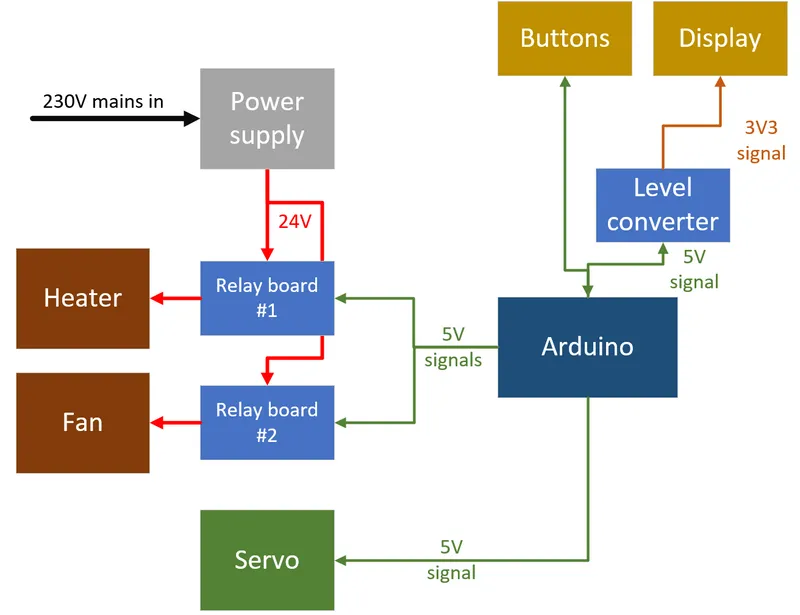
Note: there's a level converter for the display. If you need one depends on the exact display you're using - some have onboard level converters, some don't. My display did not work with 5V logic, so I had to use one.
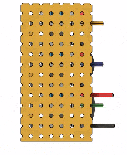
Fritzing-schematic:
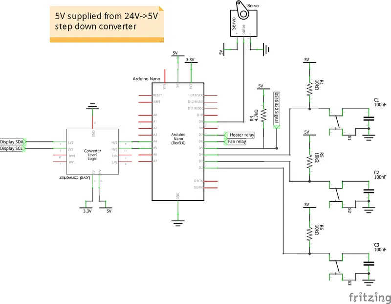
The schematic shows every component except the relay modules and the step down converter.
I'll include the Fritzing file, should you need it.
The debouncing of the buttons is done in hardware by a 0.1uF capactitor, because I've had good experiences with this solution and it reduces the complexity of the software for basically free.
Overview of the hardware:
As mentioned earlier, everything is attached to the Original enclosure itself, as its modding capabilities allow for easy attaching and cable routing.
Since Prusa released STEP-files of the enclosure recently, but not a complete assembly, I rebuilt the whole enclosure in Fusion360 as assembly (Printables link) so I could easily model the parts to exactly fit the enclosure.
Parts to print:
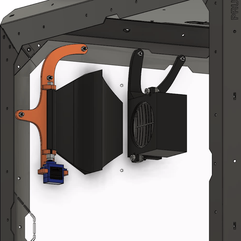
- Heater mounting
- Attaches the heater and fan to the enclosure near the exhaust-port.
- Needs to be printed with ASA or something else which can withstand high temperatures >80°C. If you have the option, ideally you would use PC / PC-CF / PA-CF or something else with a temperature rating of >95°C.
- Ideally printed with 100% infill, at least the first few mm and the “arms”.
- Flap/servo mounting
- Attaches the flap and servo to the backside of the enclosure. The hinge can be printed out of PETG, but the flap needs to be ASA, again for temperature reasons, as hot air will be blown on it. Again, if you can use something with a temperature rating of >95°C.
- New flap design: I used 10% gyroid infill and 100% around the threading, 2 perimeters.
Old flap design: Use 100% infill and supports for the flap.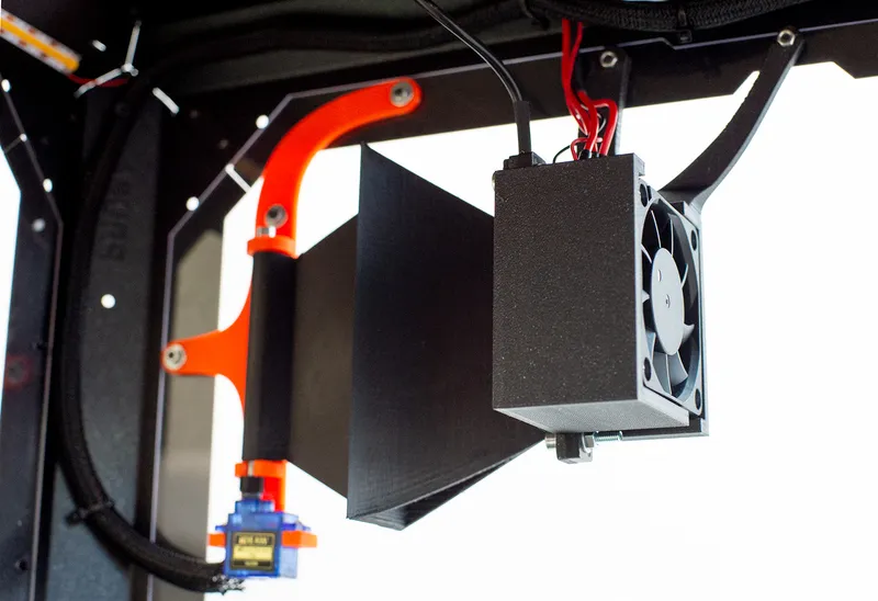
Parts 1 & 2 (old flap design) in my enclosure
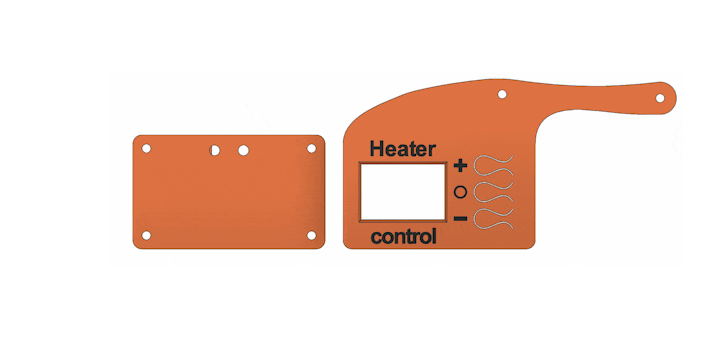
- Display/button casing
- Attaches the display and the buttons to the front of the case. As this is the only part the user acts directly with, I positioned it directly besides the original temperature/humidity sensor so it's easily reachable.
- Print with 100% infill, material does not really matter.
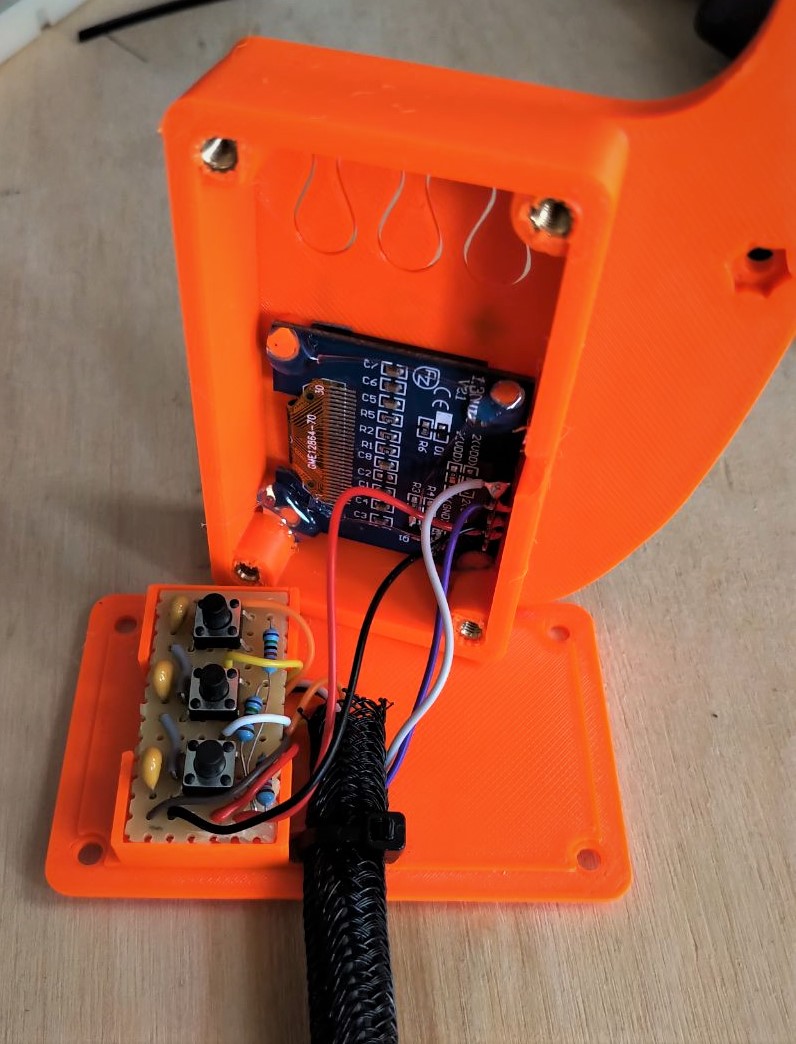
Inside of the display casing - for another picture look in the beginning of the post
- As you can see in the other pictures, I printed the text in another color than the casing itself. You don't need a MMU for this, it's easy to change the filament yourself these few times. If you don't know how, here's a guide: Forum-link
- Electronics casing
- A simple case for the electronics, namely the Arduino, the relays and the step down converter. Attaches on the backside of the enclosure besides the powersupply of the printer.
- Print with 100% infill, material does not really matter.
- Powersuppy mounts
- 3 small parts to hold the 24V-powersupply on the backside of the enclosure. Connects with 3x M4x10 screws to the PSU and with 4x M3x10 screws to the enclosure.
- Print with 100% infill, material does not really matter.
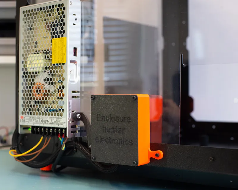
Electronics casing and PSU with holders on the backside of the enclosure
- Servo-adapter
- Connects the bottom M4-screw which is screwed and glued into the flap to the servo. Needs to be superglued to the servo.
- Use 100% infill, material does not matter, I used ASA. Probably PLA wouldn't be the best idea for long term use.
Building instructions:
Assembling the whole system is actually pretty easy, the hardest part is a bit of soldering.
Because I do not expect anyone to replicate this thing exactly the same way, mainly because parts availability (especially the heater/fan-combo) varies greatly around the world, I won't provide exact instructions for building but some GIFs that show the underlying process.
Printing all the parts
To begin you will need to print all needed parts. As you probably have to change some parts to fit your exact needs, go ahead and download either the full assembly as Fusion project or STEP file or the single part you need.
Assemble each component
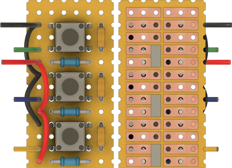
Button PCB
The button board needs to be made by you, the schematic can be seen above.
Because it's hard to make good schematics for breadboards, I made a complete model of the board in Fusion. You can either use the pictures here or download the full fusion model (or STEP) so you can easily see what to solder where.
In the model, the color-coding of the wires is:
- Red: +5V
- Black: GND
- Yellow: Up-button
- Blue: Select-button
- Green: Down-button
In the following picture, the board is turned around, so you can see both sides exactly as you would see them in reality at once. The 3 grey rectangles are solder bridges, which you need to make.
Display unit
I started by assembling the display-unit. Solder your buttons to your PCB, the space in my design fits the buttons, the PullUp resistors and the debouncing capacitors snugly but easily. Remember routing your signal cables out of the unit. Also solder the signal and power wires to the display and route the cables as well.
To assemble the box I prepared holes for M3 hot melt inserts, so that the backside can be screwed on nicely.
Also, I printed the text on the front in a different color (see above) so it looks nice - but this is completely optional.
Additionally, the design intends for two M3 nuts to be pressed into the plastic, which I forgot to include in the animation…
Electronics Box
The idea is the same as before, the backside gets screwed into 4x M3 hotmelt inserts. I won't go into detail regarding soldering here, as your setup will most likely vary.
Try to be smarter than me and route the cables through the hole before soldering, otherwise you have to either cut a slot into the box or resolder some stuff. I may or may not had to cut a slot into mine…

Heater / Flap assembly
At this point this should be self-explanatory. The special part here is the connection between the lower screw in the flap and the servo. I designed an adapter that gets glued onto the servo (because they are so cheap that I think it's okay to permanently attach it…) and that fits into the hex-head of the screw perfectly, so that the torque can be transferred. If you don't like this design, there is a remix with a slightly different design of the flap with a different way to connect to the servo.
To make the installation easier, the bottom slot on the hinge is, well, a slot and not just a hole. This way you can screw into the flap, adjust the length that sticks out, glue the adapter on the servo, insert the screwhead into the adapter and then slot the whole assembly into the hinge.
After that, you can mount the servo with its screws and then mount everything into the backside window.
The heater gets screwed on as shown in the GIF. Please note that in the animation there is a very small part - the holder for the temperature probe in front of the heater - that I forgot to include. You can see the part and the sensor in the picture above.
Powersupply
Mounting the PSU is easy. I highly recommend going with a good model, like one from MeanWell with overcurrent-, short circuit and temperature protection. They are not too expensive but will potentially save your electronics in case of a fault.
When screwing the holders to the PSU itself, follow the manufacturerers rules on maximum screw length!
For mounting the PSU to the enclosoure I used M3x12 screws and M3 nuts and washers on the inside.

Routing cables
After installing every part, you can begin sleeving the cables and routing them through the enclosure. There is no right way to do it, just route everything so that there's no interference with anything in your specific setup.
In the animation at the very top you can see how I routed my cables.
The cablesleeve can be attached with zipties to the enclosure frame.
Software:
Current state: Fully working!
I wrote software for the Arduino which acts as a simple user interface for controlling the system.
When starting up, the system is in idle state doing nothing but closing the vent once.
Pressing the middle button will cycle through the 4 currently implemented modes:
Heating:
Closes the vent, starts the heater and fan and heats the enclosure to the set temperature. You can set the temperature with the upper (+) and lower (-) buttons by changing it in 5°C (customizable) steps. The maximum temperature that can be set is 45°C.
When the target temperature is reached, the heater and fan will turn off. They will turn on again, if the temperature inside the enclosure is 2-3°C below the the target.
Cooling:
Opens the vent and starts the fan to blow out air. Especially useful when you have to print a low-temp material (like TPU) directly after a high-temp one (like PA11), as I often have to do.
Reminder: This system cannot actually “cool” your enclosure to lower-than-ambient temperatures, as it can just blow heat outside the enclosure and replace the inside-air with ambient-air.
Fan / Circulation:
Closes the vent and turns the heater off while starting the fan. This is meant to evenly distribute any heat inside the enclosure, which can be beneficial for large prints, even if you don't need any extra heat.
Idle:
Only closes the vent and does nothing else. It's like it's not even there!
Hackability:
I love the open source mentality. That's why I tried to make the whole thing as modular and easy to not only reproduce, but also modify to your own needs.
As the hardware is built from easily exchangeable parts, changing the software to your liking should be easy enough!
The code is written using PlatformIO, that's why I'll provide my platformio.ini, so that library import can be easier for you.
Other notes:
As I wrote the software from scratch and I am not a real programmer, you can expect that the code-quality won't be top notch.
There's some things I know could be better, but some fancy tricks are omitted so it is easier to understand for other people, who might just begin to code.
I tried to document as much and as clear as I could, so the structure should be easy to get into within a few minutes.
Getting the software:
The PlatformIO project is fully available on Github.
However, I try to upload the code here as well, as some people might not know how to deal with GitHub.
Warnings and disclaimer:
Working with 110/230V is dangerous. When using a powersupply like the one I used always make sure to protect any points carrying live voltage from being accidentaly touched.
You should probably use a fused and switchable input with a stadard plug which can be wired to the powersupply.
Everything here (except otherwise noted, see below) is designed by - and mainly for - myself. I cannot take any responsibility for any hazards, damages or dangers that may occur. Do not leave the heater unattended. Everything I release here is released without any warranties.
Everything written here depicts my personal opinion and should not be confused with any professional advice.
THE CONSTRUCTION FILES ARE PROVIDED "AS IS". THE AUTHOR DOES NOT PURPORT AND DOES NOT REPRESENT, WHETHER EXPRESSED OR IMPLIED, THAT THE CONSTRUCTION FILES ARE FREE OF ERRORS, FREE OF FAULTS AND USABLE FOR ANY PURPOSE: THE AUTHOR IS NOT AN EXPERT IN 3D CONSTRUCTION AND NO EXPERT IN ENGINEERING. THE AUTHOR DOES NOT ACCEPT ANY RESPONSIBILITY NOR LIABILITY OF ANY KIND FOR THE USE OF THE CONSTRUCTION FILES, REGARDLESS OF THE PURPOSE; THE LIABILITY FOR ANY DIRECT AND INDIRECT DAMAGE IS DECLINED.
The use of trademarks, tradenames and other marks of third parties, if any, serves solely descriptive purposes pertaining to the construction files; the trademarks, tradenames and other marks of third parties are and remain the sole property of such third parties.
Attributions and licenses:
I used multiple pre-made models from different sources under different licenses.
As I release the whole Fusion360 assembly file, you need to be aware that the different parts inside the assembly fall under different licenses.
Prusa Enclosure Parts:
Source on GitHub (link), is licensed unter GPL-3.0
Relay module:
From GrabCad by user Gistroy: Part link
PTC Ceramic Heater:
From GrabCad by user Kim Sihota: Part link
60mm Fan:
From GrabCad by user Manesh Kumar K: Part link
MeanWell Powersupply:
Directly from MeanWell (link)
SG90 Servo:
From GrabCad by user Mehmet Berkay: Part link
Screws, nuts, washers:
Imported from Fusions McMaster Carr library
As far as I understand, the GrabCAD license does not cover commercial use of these models.
I will publish all of the models I designed under the in the Printables-Model-Entry mentioned license, but note that the shown license does not cover the parts from other creators in the assembly.
That's why I will release two versions of the Fusion archive:
- Just the parts I designed, these are under the license mentioned in the Printables entry
- Everything including the enclosure and all other parts, just for your reference
Thank you to @Ossum for finding links to Amazon US!
State of the project:
The project is now done. In its current state, it is completely reproducable and works as intended. The software works (for me anyways) and I am using this system productively.
Currently I'm thinking about changing some things in the electronics, mainly controlling the heater with a MOSFET and PWM instead of a relay and also replacing the Nano with something like an ESP32 to integrate remote control.
Update log:
03/dec/2023: Updated to version 1.4:
Software:
- Added Fahrenheit mode
- Added serial logging of temperature values
Thank you to @Ossum for contributing via GitHub!
11/nov/2023: Updated to version 1.3.2:
Software:
- Fixed handling of temperatures above 100°C.
- Fixed a bug in the sensor-error message.
Thank you to @Ossum for contributing via GitHub!
10/nov/2023: Updated to version 1.3.1:
Nothing changed feature wise, but I split the software into two files:
- main.cpp
- configuration.h
The configuration.h contains all user-specific parameters like the sensor addresses, the pin definitions, servo positions and so on.
This way, if someone wants to contribute something to the code via GitHub, they are able to easily change the main.cpp without getting their address overwritten with every pull.
Note: The configuration.h comes as configuration-sample.h and needs to be renamed to configuration.h once. After that, it will be included in the main.cpp as configuration.h but is also ignored for any further Git commits.
29/oct/2023: Updated to version 1.3:
Hardware:
- Display case front: Slightly changed the position of the “o” marker next to the middle button, as it was misaligned after the latest change.
Software:
- Updated temperature error to blink/flash when triggered.
- Updated handling of recovery of temperature-errors (sometimes the error would be persistent after a power-cycle, even if the temperature was in-spec again).
- Added configurable to modify delay time for servo-movement.
- Servo now only closes once during startup and does not try to ram into sidepanel too much.
26/oct/2023: Updated to version 1.2:
Hardware:
- Flap: Slightly changed design of the flap for better airflow. Inspired by this remix.
- Display case front: Slightly changed the size of the cutout for the display, as it was 4mm too high before. Should be perfect now, at least for the display I'm using.
Software:
- Adjusted trigger-temperature for overtemp error. Turns out that 90°C triggers the system too early.
Printables-entry:
- Added STEP files for individual parts/assemblies.
- (Added code to GitHub)
25/oct/2023: Updated to version 1.1:
Added new features:
- Overtemperature error handling: Display shows an error message when the case temperature reaches 50°C or the heater reaches 90°C. Disables the heater and locks the system, so that a power-cycle is needed to start the heater again. This is done for safety.
- Sensor error handling: If there is no sensor detected (wrong connections, missing 4k7 PullUp, wrong addresses…), the system throws an error and turns of the heater. Also locks the system until a power-cycle.
- Lowered RAM-usage, so there's more space to add features for anyone!
Fixed some bugs:
- Previously, the target-temperature was being able to be set to 50°C while still showing 45°C - This is not the case anymore.
- Fixed a RAM overflow that would lock the system when in a specific state for a few hours.
17/oct/2023: Updated software to version 1.0:
I finally had time to add the missing features and modes. Now the system starts in idle mode doing nothing but closing the vent. After pressing the middle button once, the system changes to heating mode and the target temperature can be set. Further presses cycle to the modes: Heating, Cooling, Fan only, Idle. When I find the time, I will add more descriptions and pictures of the new software.
12/sep/2023: Changed license
Changed license from CC 4.0 Attribution to GNU GPL 3.0, as this is (mainly) built on the original parts by Prusa which require sharing under the same license. I just mis-clicked during selecting the first time, whoops.
Tags
Model origin
The author marked this model as their own original creation.


