Sequential Shifter
Description
PDFChangelog v3 Release
- Removed the need for supports using the bore trick
- Adjusted some bridge problem above the MCU housing
- Removed front mounting solution with M3
Changelog v2 Release
- Added a cover on the top with a + and - sign
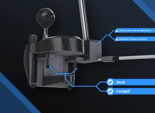
- The deck is now re-inforced to prevent the MCU from breaking the print
- Added mounting holes in the front and on the sides. Front for M3 screws, sides for M6 screws.
- Made a path for the wires to go inside the Nut Side part all the way into the MCU
There are various models and ideas out there to make a sequential shifter.
I wanted to make one with the hardware I had at hand, so I modeled it from the ground up to practice my Fusion skills.
BOM
- 2 * Micro Switches (I use these from AliExpress)
- 1 * Arduino Pro Micro (I use this clone from AliExpress)
- 2 * 15mm Springs ; 9mm OD (I use these from AliExpress, the 0.7mm WD)
- 4 * 45mm+ M3 Screws & Nuts
- 4 * 12mm M3 Screws
- 4 * M3 Heat Set Inserts
- 1 * 40mm+ M6 Screw & Nut
- 1 * 200mm Aluminum Tube (16mm OD )
- Essentials like wires, soldering iron, super glue etc.
ARDUINO CODE
Made with the help of ChatGPT as I don't program
Link: https://pastebin.com/HETffZnA
PRINT SETTINGS
Use support for the holes that have the screw stopper & nut stopper.
Otherwise you can print this with whatever settings you prefer but I suggest the following:
- 4 Perimeters
- 0.2 Layer height
- 20% Infill
The orientation of the parts allow you to not worry about anything breaking (supposedly) so you can use whichever material you prefer.
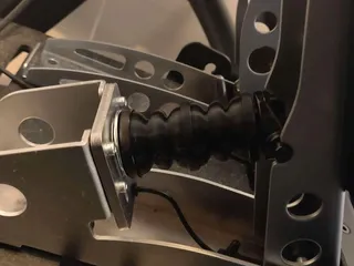
Mine in the pictures is printed off entirely PLA and works perfectly no crack to be seen or heard.
ASSEMBLY
It's pretty straight forward as you can see from the pictures attached to the post.
- Put the heatset inserts under the parts Nuts Side & Screw Side
- Install the switches with the wires going through the holes under them or inside the pathway
- Wire on pins 5 & 8. And use a GND pin for each switch.
- Install the springs and add some super glue so they don't have play
- Drill a 6mm hole in your tube centered at around 55m of height
- Press fit the handleonto the tube
- -Optional- You can add washers on the sides of the aluminum tube (printable ones available)
- Attach both pannels together securing everything in place
- Attach deck pannel and make sure the wires are under the other pannels
You should be all up and running now !
Let me know if you encounter any problems.
Tags
Model origin
The author marked this model as their own original creation.


