The "Help! I can't decide!" Lack enclosure v2

Description
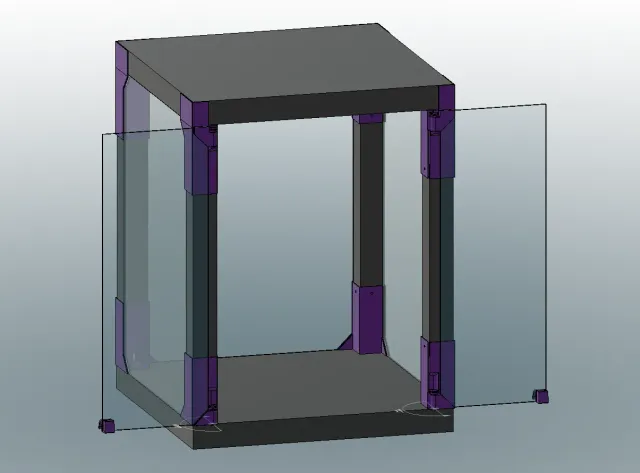
PDFThis is version 2 of my "Help! I can't decide!" Lack enclosure with improved rigidity, stability and flexibility!
I wanted an enclosure that I could easily dismantle to service the printer. I couldn't make a choice between an enclosure with a removable top or a removable body, so I created one that does both! I also wanted an enclosure that would be big enough to fit a spool (or drawers!) inside and would be able to seal well.
Features
- 624 mm inner volume height (the files can easily be edited to change this, but be mindful of the length of screwdriver that it will require)
- 180° door opening
- Easy printer maintenance : The top, the doors, the legs and the panes are all easily removable
- Maximum self-contained inner volume with the panes sitting at the very edge of the table
- Good seal with the panels sitting flush against the legs
- Accommodates acrylic panel thickness up to 5 mm
- Customizable screw hole sizes
Required hardware
- 32 round head (not countersunk) screws with a diameter of up to 5.2 mm
- Acrylic panels up to 5 mm in thickness (For dimensions, see assembly instructions)
- 2 20x10x5 mm magnets
- A 4.5" or 110 mm long (or longer) drill bit or screwdriver
- A drill
- A drill bit that is a little smaller than the stem of your screws
- Utility knife
Print instructions
Use the paint function in your slicer to paint the location of the seams to the location shown in blue in the pictures.
The folder names indicate the layer height at which the parts are meant to be printed. The file names indicate how many times each part needs to be printed.
The inserts are available in 3 tolerances. 0.2mm, 0.15mm and 0.1mm. This choice depends on your printer's accuracy. Pick whichever one allows you to mate parts without force but without wiggling room (run tests if required).
Most parts were meant to be printed with a 0.4mm layer height. Those parts can also be printed at any layer height that 0.4 divides evenly by (i.e. 0.2 or 0.1).
Aim for a wall thickness of 1.2mm or more. I printed all parts with 2 walls on a 0.6mm nozzle and they feel very sturdy.
The hinges require a well calibrated printer. Make sure that your extrusion multiplier is set properly. Print one by itself and if you are able to break it, print the other 3.
All parts should be printed with 15% infill.
The 3mf files do NOT contain slicer data. They are model files that were exported from Fusion 360. Upon import, PrusaSlicer will tell you that the file seems to be defined in inches. Click No. Then it will tell you that the file contains several objects positioned at multiple heights. Click Yes.
You can customize the screw hole sizes by deleting rings around the screw holes. I suggest using a hole size that will allow you to have a little bit of wiggle room to adjust the location of the inserts. The smallest hole size would fit screws that are rather small for this purpose, but I made them this small in case smaller screws are the only thing someone can get. Ideally you should use the medium or large hole size.
Post-processing
The hinges print as one piece that needs to be broken. If you are unable to break them, it is likely because your extrusion multiplier is too high. Print them again with a lower extrusion multiplier.
There are little tabs in-between the triangles on the mounts that need to be cut away. Those exist simply to prevent the print from lifting. In theory you can leave those that are on the bottom mounts, but you will need to take the added height (0.4 mm) into account when measuring your panels.
Assembly instructions :
1) Screw the thumb crews into each of the mounts. It may require a bit of force at first, but after they are broken in they should turn smoothly.
2) Use the guide to locate the holes for the inserts. Put the guide against each corner of the table tops and mark down the holes with a pencil. Remember! Don't mark the same side on both table tops! One will have the inserts screwed into the top, the other into the bottom.
3) Use a screw and a blunt object (like the handle of your screwdriver) to punch a small location hole in the middle of the marks. This will serve to keep the drill bit steady when you start drilling the holes.
4) Drill the pilot holes.
5) Screw the inserts into the table tops. Refer to the pictures to know the location for each insert.
6) Use the guide to drill holes into both ends of each leg. Make sure that they line up!
7) Screw a screw about 1 cm or 3/8" into each hole, then unscrew it.
8) Screw the mounts into the legs. Refer to the pictures to know which mounts to pair together.
9) Insert the hinges into the mounts and push them in fully. There are crush ribs at the bottom of the hinge sockets so pushing the hinge in fully will require some force. Be mindful of the orientation. The threaded hole for the thumb screws should be facing inwards.
10) Place the printer on the base.
11) Route the cables through the holed insert.
12) Insert the hat into the holed insert.
13) Place the legs onto the inserts.
14) Put the top on.
15.1) Measure the distance between each leg on each side. Measure at the top and measure at the bottom. If the measurements differ from top to bottom, ensure that the legs are well seated into the mounts. If there is still a difference, pick the smallest measurement to make sure your panels will fit. This will be the width of your panels.
15.2) Measure the distance between the top and the bottom of the table tops. This will be the height of your panels.
15.3) For the doors, it is slightly trickier. The design calls for the following clearances :
- 0.5 mm between the doors and the legs
- 2.4 mm between the top and bottom of the doors and the table tops
- 1 mm of clearance between the doors
Measure the width and the height and subtract these numbers from your measurements i.e. (height - 2 * 2.4) and (width - 0.5 * 2 - 1)
In the CAD design, the side panels are 624 mm x 448 mm and the doors are 619.2mm x 223.5 mm. However, CAD is not real life and real life is imperfect. You should use your own measurements and calculations to figure out the size of the door panels and you must take into account potential cutting errors.
Use your best judgement in determining the final dimensions of your panels.
Once you are ready to install the panels :
16) Remove the top.
17) Insert the panels into the triangles from the top.
18) Put the top back on.
19) Screw in the screws to hold the panels in place.
20) Insert the doors panels into the door triangles.
21) Screw in the screws to hold the panels in place.
23) Insert the handles onto the doors so that they will sit at the very edge of the doors, but not quite meet. You can install them at the top or at the bottom of the doors, it is up to you.
Tags
Model origin
The author marked this model as their own original creation.