FT EMS 350 (Electronics Management System)

Description
PDFNOTE
Updated V2 of the frame for the Voron 2.4 has been released. Please use that as it has a number of improvements. https://www.printables.com/model/816080-ft-ems-v24-350-v2
The cable ducts that were designed for EMS 300 have now been backported to EMS 350. Use the ducts from the folders labeled “Cable Ducts V2” and “Lids V2”. These cable ducts are a lot stronger and taller to cater for those that do not use a toolhead board.
INTRODUCTION
Not a fan of DIN rails and VHB tape - Sorry VoronDesign team. So I have designed my own printable modification to properly mount and manage the cabling required to build a Voron 2.4 350mm printer. This is being released as Beta 2 until I am happy with the feedback and will tweak as per feedback.
THE DESIGN
This design was extended from the V0.2 and Switchwire Electronics Management solutions I previously created. It is designed to remove the need for DIN rails and especially VHB tape (Yes VHB tape has its uses but NOT for mounting electronics!). The components are designed and mounted on hex stand-offs and can be moved to wherever your heart desires. My initial implementation is intended as an example but it really is up to the end user to place the parts where they want them to be located and print only what is needed.
BOM
- 16 x M5x10 BHCS
- 4 x M5x16 BHCS
- A lot of heatsets
- M3x6
- M3x8
INSTALLATION INSTRUCTIONS
EMS is designed to be extremely flexible as to let the user decide what hardware to use on the printer. Therefore we have created a mounts repository where power supply, controller board, expansion board and single board computers (Raspberry Pi) mounts are stored. Please visit our mounts repository to download universal cable ducts and mounts for the hardware you intend to install - https://www.printables.com/model/558357-ft-ems-mounts-repository
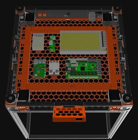
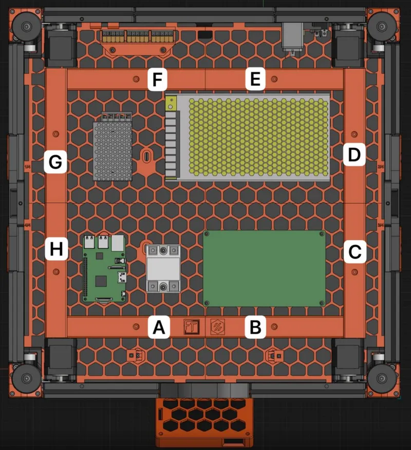
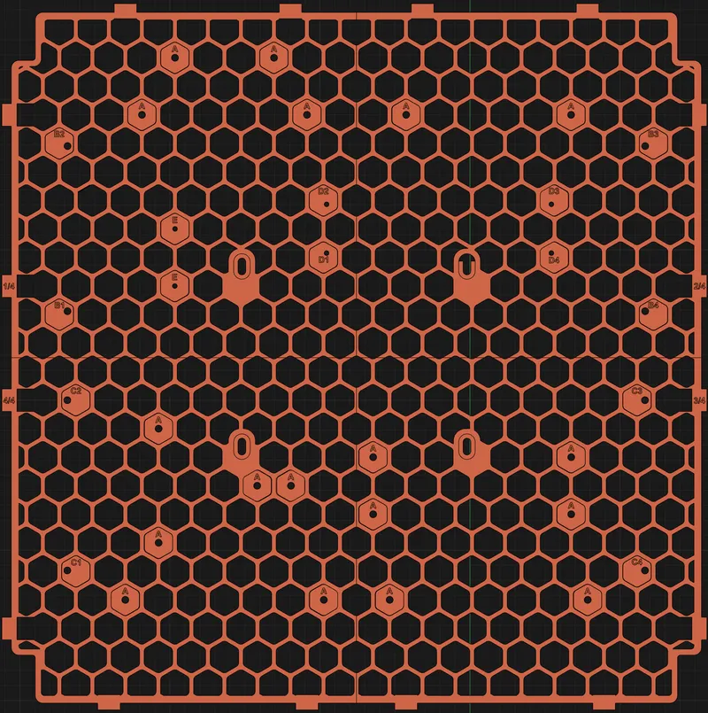
Which hex mounts do I need? Here is a breakdown of what each are used for: -
- Mount A = hole directly in the center of the hex and the screw is inserted from the mount side
- Mount B = hole is with a 5mm offset and the screw is inserted from the mount side. Depending on which direction you need the offset you can rotate the hex so its actually 5mm offset in 6 directions!
- Mount C = Cable tie in the center of the hex in the vertical orientation
- Mount D = Cable tie in the center of the hex in the horizontal orientation
- Mount E = These are used for electronic mounts that have a heat insert in them. The screw will go through the center of the hex from behind into the mount. These are typically used for SSR and some PSU mounts.
- Mount F = These are used for electronic mounts that have a heat insert in them. The screw will go through the center of the hex from behind into the mount. These are typically used for SSR and some PSU mounts.
- EMS Bolt = this is used for awkward mounts and load into the channel on the electronics mount with an M3 heat thread insert preloaded. These work in combination of Mount E and F.
I recommend printing the whole set of parts and test fit them outside of the printer prior to installation. This will serve as a double check to ensure that all the correct parts are printed and prepared.
- Prepare all of the parts and insert the heat-sets where needed.
- Assemble the entire mod outside of the frame prior to installation.
- The parts are mounted using the hex plug-ins labeled A to E
- Insert heatset inserts for all hexes with the exception of parts labeled D & E
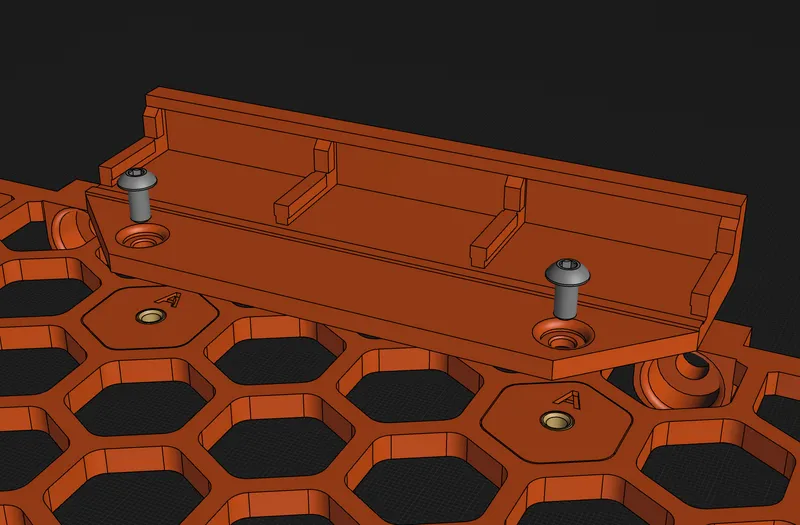
- Insert the hex from behind the frame, align the front piece (cable duct or mounts) and insert M3x6 screws for cable ducts and M3x8 for electronic mounts as shown in the image below
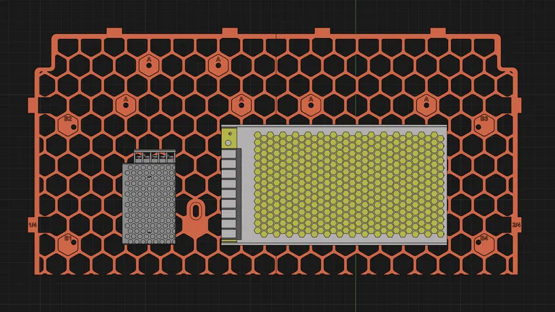
- Mount the RS 25 PSU (5V) to frame ¼.
- Mount the LRS 200 PSU to frame 1/4 and 2/4.
- Mount the Wago mount and Cable Ducts C & D onto panel 1/4 and E & F on panel 2/4 as shown using the frame mount bolt-ons.
- Use the reference image for installing Cable Ducts & Lids V2. These now work with the Mount A hex.
- Reference for bolt-ons from the rear
- Screw in the M5x16 BHCS screw that will be mounted under the LRS 200 (you will not be able to tighten this screw all the way as it is covered by the PSU so screw it down enough so that the frame can slide onto it).
- Insert 8 M5 T-Nuts for both 1/4 and 2/4 (4 each) and slide them into place.
- Mount both 1/4 and 2/4 at the same time and be careful to slide the centre mount on panel 2/4 to the M5x16 BHCS previously inserted.
- Secure the 2 parts of the frame with 10 x M5x10 BHCS screws.
- Screw down the centre piece of frame 1/4 using an M5x16 BHCS screw.
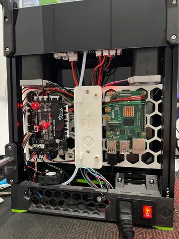
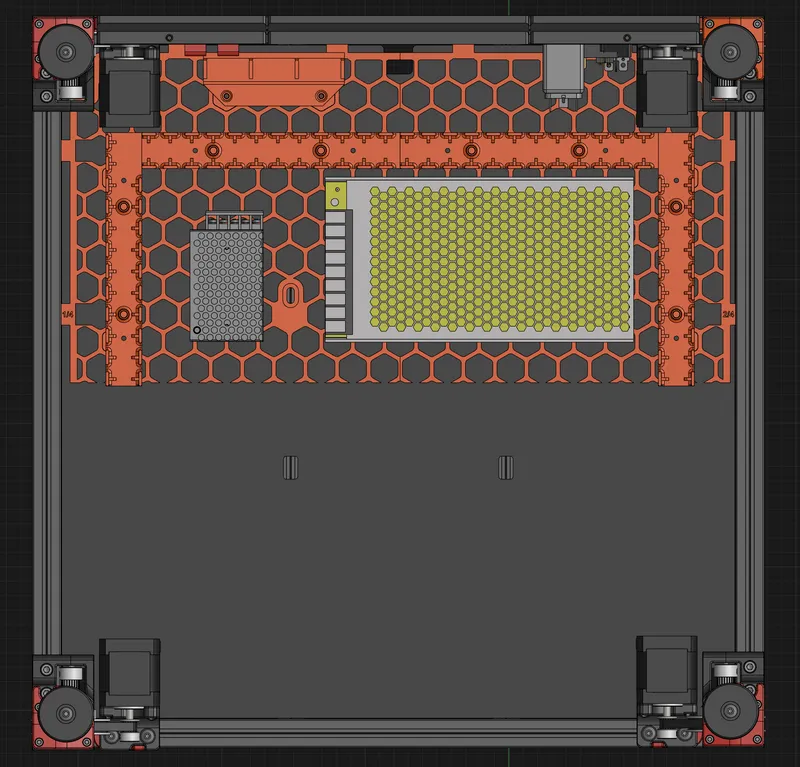
- Once this is mounted it should look like so: -
Hope that you appreciate the amount of time and effort to turn around such a big modification. If you like my designs and would like to contribute to fund filaments and other equipment required for prototyping, please do so at my paypal.me or Ko-fi. Your support is greatly appreciated :)
Do let me know what other boards you intend to mount.
Should you have any questions you can reach out to us via Discord - https://discord.gg/fizzystech
CHANGE LOG
8-Sep-2023
- Added updated cable ducts and lids from EMS 300 as they are much stronger and taller for those who do not use a toolhead board and require the extra space for wiring.
Tags
Model origin
The author marked this model as their own original creation.