Parameterized F360 Anderson PowerPole Fuse Block
Description
PDF7/27/2023 update
- Tweaked spacing for layout
- Added new version using pins for PowerPole pair retension rather than the “click-in” method. Can make assembly easier.
7/29/2023 update
- Added a “shell pusher” to assist in assembly of the “click-in” model.
The Fusion 360 file attached is for a customizeable Anderson PowerPole fuse block. You will need to open the file in Fusion 360 to generate the files needed for printing.
The user can change the number of connectors on the fuse block. To do this, use the “Modify” pulldown & select “fx change parameters”. This opens the parameters dialogue. The user parameter “circuits” controls the number of fuse+PowerPole pairs that will be included on the block.
The fuse holder is composed of a pair of ¼" female quick connects that are pressed into the block.
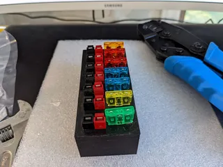
The “click-in” version model assembly involves inserting PowerPole shells and fuse holder assemblies into the block. A pair of PowerPole shells will snap into the rectangular openings with some effort. The red shell should be adjacent to the fuse holder position (I am assuming use of the ARRL “red right tongue top” configuration).
Installation may be easier if the black shell is first placed into position with the side depression positioned over the ridge at the opening side. The red shell side tab can then be started into the black shell slot while being fitted into the rectangular opening. Some force & “jiggling” may be needed for them to snap into place.
The “shell pusher” tool can be used to assist in assembly on the “click-in” model. Best used seated to the red shell with the red & black shells just barely engaged. Use it to position the pair as described above & to apply pressure to the red shell until engagement. See pics
The alternative pinned version model uses lengths of filament as pins to retain the PowerPole pairs, providing holes in the model for their passage. Filament pins pass through the center “hole” of the PP pair and through the half circle depressions on either side. Position a PP pair in the block & pass a pin through the center hole, repeat until all pairs are in place. Finish by adding pins to either side. Trim pins to length & secure them in place with glue or by melting the end into place. See picture for pinned assembly reference.
Crimp or solder wires to the female quick connects prior to insertion. After insertion, solder all fuse holder wires along the outer wall to a buss connection. You can use solid wire or battery connection ribbon for this. The wire from the inner fuse holder should get a PowerPole contact crimped to the end. This is then inserted into the red PowerPole shell.
Crimp short wires to PowerPole contacts for insertion into the black PowerPole shells. These wires should all be joined in a buss connection, just like the outside fuse holder wires.
The included pictures should provide context for the above instructions. The black shell wires had not yet been added when the picture was taken.
After assembling the connectors & wiring, the “lid” can be glued in place to close the bottom opening.
I suggest a minimum of 3 walls when printing. Infill is not critical, I used 20%. The pictures were of prints in ASA (white) and PETG (red). I found silicon coated, fine stranded copper wire to be flexible enough & heat resistant enough for easy soldering and assembly.
Tags
Model origin
The author marked this model as their own original creation.


