Smart Lander for Investigating Moon (SLIM) 1:20 model

Description
PDFThe Japanese Smart Lander for Investigating Moon (SLIM) is set to be launched on board of an H-IIA rocket alongside XRISM in late August 2023. Developed by the Japan Aerospace Exploration Agency (JAXA), the lander will try to demonstrate precision landing technology.
More details can be found:
- on the mission website: https://www.isas.jaxa.jp/home/slim/SLIM/index.html
- on the mission twitter account: https://twitter.com/SLIM_JAXA
- in English on the JAXA twitter account: https://twitter.com/JAXA_en
- in English on the JAXA website: https://global.jaxa.jp/
One difference I like between SLIM and any other soft-landing probe is its landing technique! After cancelling all its surface velocity, it will rotate and land on its side using shock absorbing pads. As a tribute to that originality the model features a desk stand representing the lunar surface on which the model can be displayed.
This 1:20 model was prepared based on the pictures and the 3D model shared by the project on social media and tries to convey as much detail as possible at this scale.
Print instructions
The different pieces are designed for FDM printers and around a layer height of 0.2mm and a nozzle diameter of 0.4mm. No support is needed.
The biggest piece is the stand that is designed to be printed vertically for a better surface finish, needing a build volume of at least 150mm horizontally and 135mm vertically. The rest of the pieces are fairly smaller but will still require a X115mm x Y85mm x Z60mm build volume.
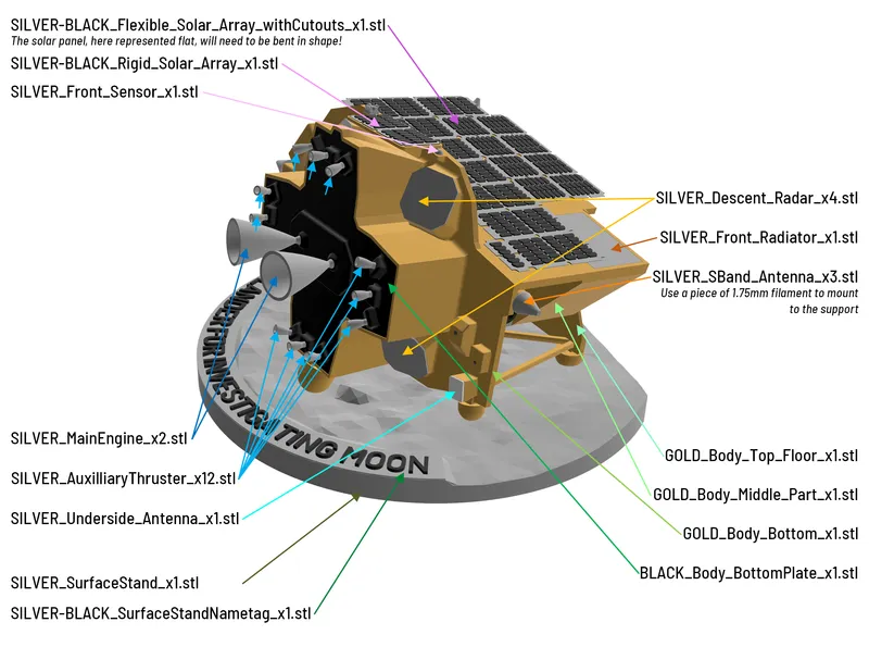
For each .stl the color(s) are indicated as a prefix in the name and the number of copies as a suffix (e.g. for "SILVER-BLACK_Rigid_Solar_Array_x1.stl”, 1 copy of the piece must be printed, with silver then black filament).
6 pieces (the 2 solar array assemblies, both parts of the LEV-1, a pair of top-floor sensors as well as the desk stand name tag) need a color change in the last few layers (2 for the solar panels and the name tag, 3 for the top-floor sensor, 10 for "SILVER-GOLD_LEV-1_Bottom_x1.stl" where the slope starts), which is easy by adding a filament change directly in your slicer.
The tolerances used are 0.2mm vertically and at least 0.07mm in-plane to provide a snug fit (keep that in mind if you want to re-scale the model!). If the tolerances are not accessible to your printer (or your printer is better tuned than my Prusa i3 MK2.5S 😉) you may have to use sandpaper or a hobby knife to adjust them until they fit and/or use (more) glue.
Printing the 2 main thrusters and the 12 auxiliary thrusters should be done vertically but can be challenging and I recommend using a brim to help adherence to the printing plate. Same story with the stand for which some additional supports can even be painted on the small sides to prevent wobbling when printing this tall and thin piece.
The solar arrays are flimsy by design, be careful when removing them from the build plate!
Assembly instructions
I recommend using common white glue (and patience 😉) to assemble the pieces instead of contact glue that often leaves white residues and can be messy.
The overall assembly is relatively easy (although I do recommend trying some of my other more simple models before attempting this one). Please refer to the 3 little montages below presenting how the different pieces are positioned with respect to each other:


Some tips and an overall assembly order to hopefully prevent some frustration:
- Assemble the Body_Bottom to the Body_Middle_Part together, then mount the trusses at the back and then add the Body_Top_Floor
- Glue the flexible solar panel on the front. I suggest to use the left border as a reference point and then bend the piece in place along the Body_Middle_Part from there. Big plastic spring clamp are almost necessary to keep everything in place! Alternatively, you may try to use small drops of contact glue in strategic places or even try to soften the piece by applying very moderate heat.
- Install the accessories, everything should be relatively straightforward.
- Note that the 3 antennas have to be assembled using small pieces of 1.75mm diameter filament.
- the MX_S-Band_Mount and the CAM_PX are glued in place by aligning them in the corners. The rest of the pieces have some alignement methods that should help with the positioning.
- If you want to paint in black the apertures on the CAM_PX and the underside of the lander, I suggest to use thick paint, as ink or runny paint have a tendency to spread between the layers by capillarity, often very disgracefully (as you may be able to see in the pictures)
- I suggest to mount and glue the thrusters to the Body_Bottom_Plate and then install them together on the rest of the model at the very end of assembly as this probably the most fragile area of the model.
- Note that on the back of the desk stand 3 slots can be filled with some rubber-like glue to prevent slipping.
Happy printing and good luck to the SLIM mission team!
Tags
Model origin
The author marked this model as their own original creation.


