Description
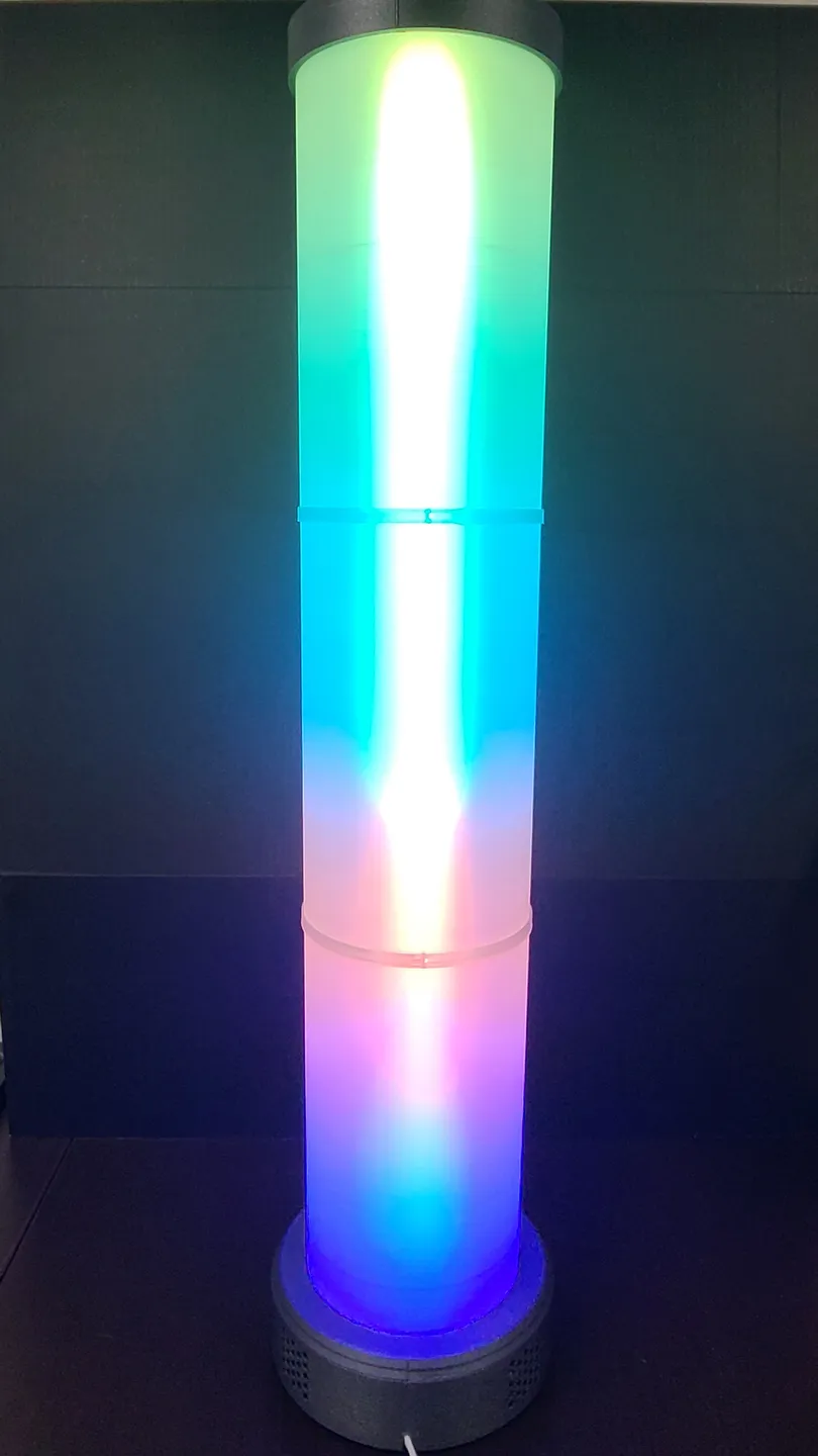
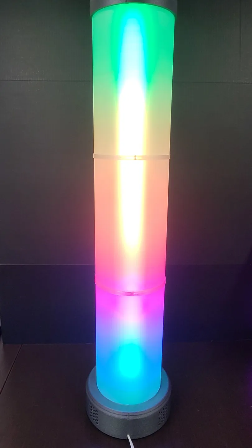
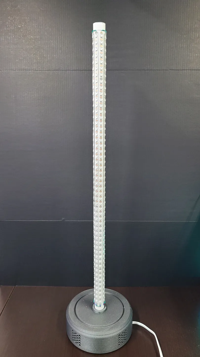
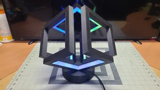
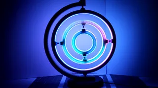
PDFI've made many led lights, most all the designs from here. This is one that's similar to others, but BIGGER :D Go big or go home right?
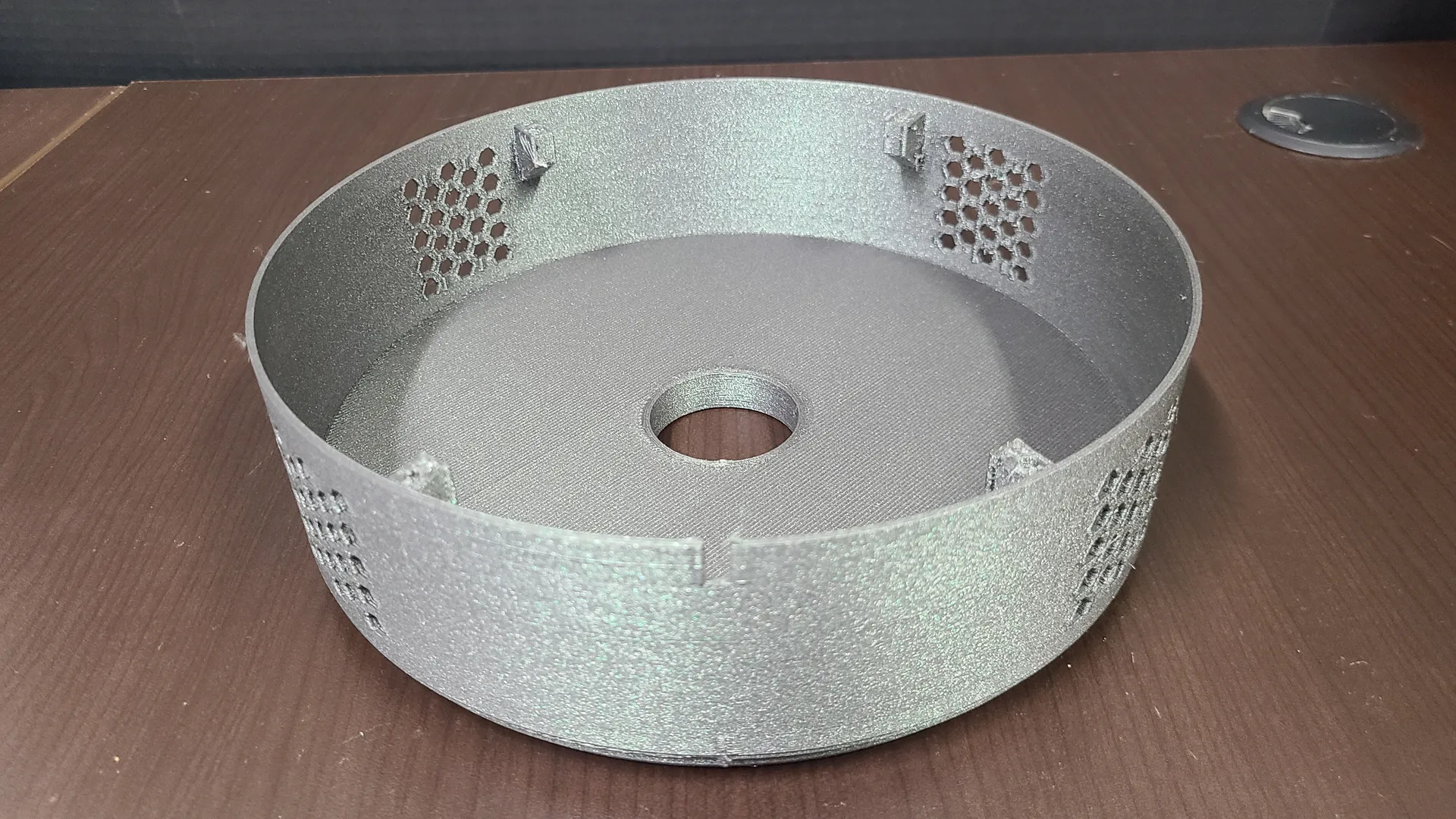
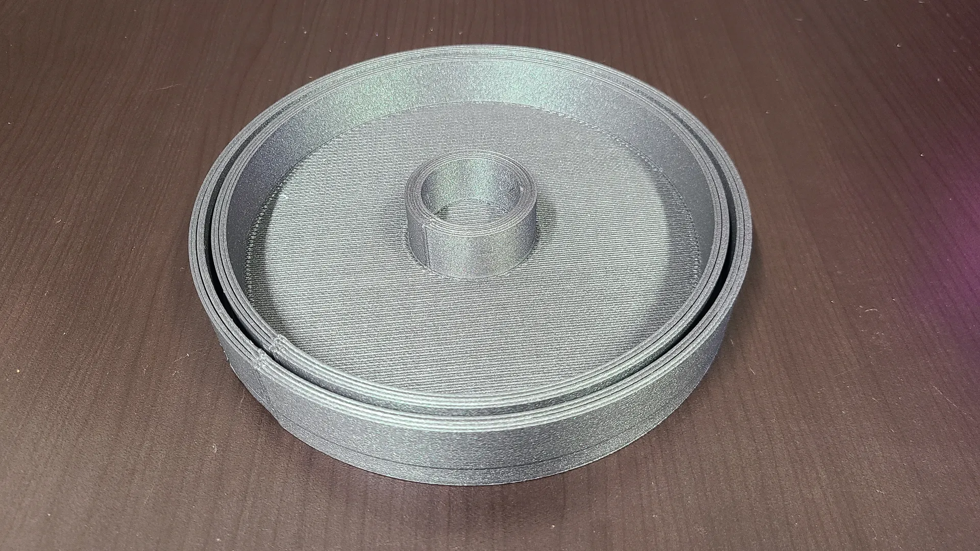
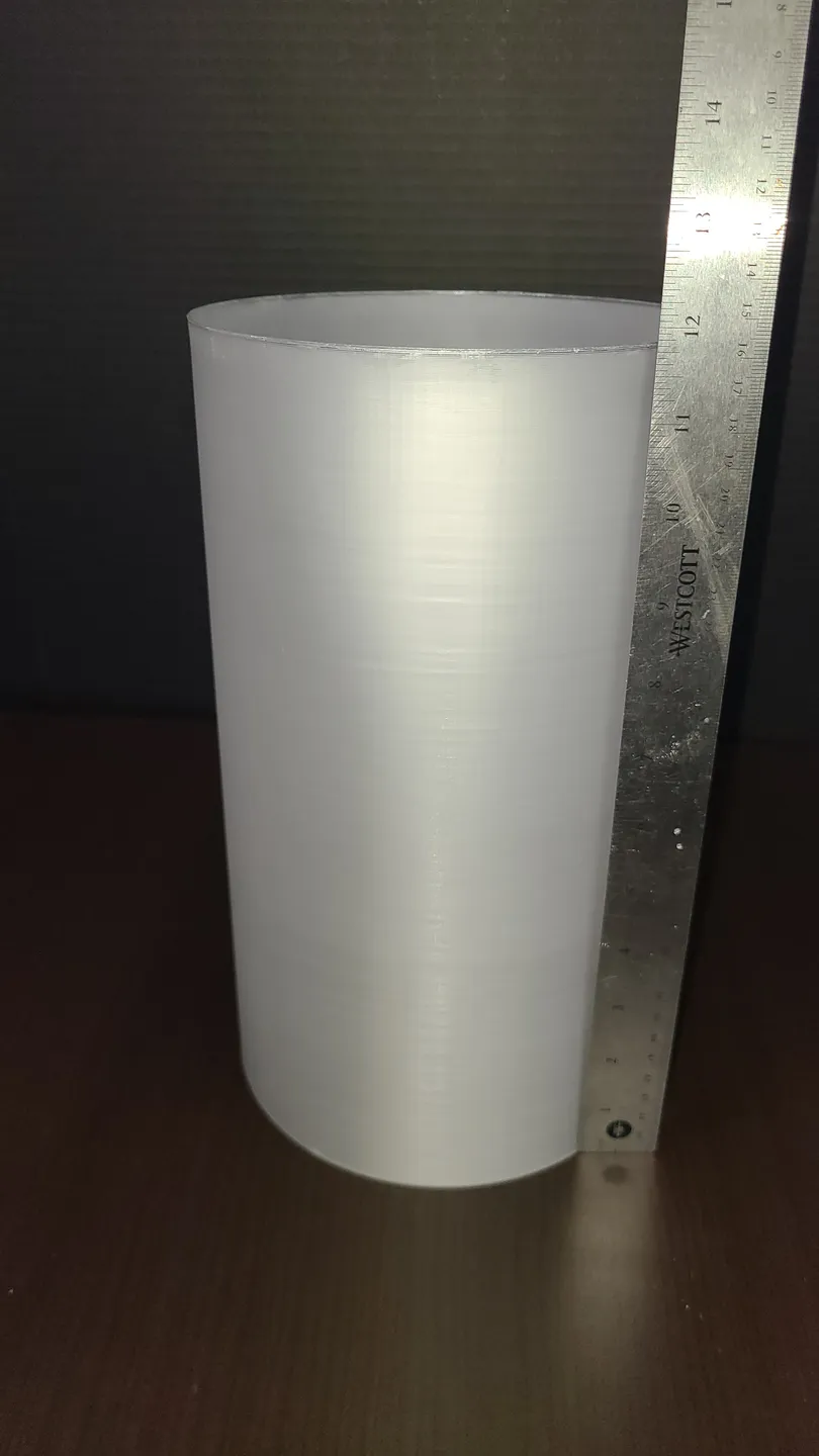
This was printed on a Kobra Max (410x410x450) , but the largest piece (the base) is 235mm so it can be printed on smaller machines. The diffusors on this are 350mm tall each. This can be easily resized for height, you will just need more connectors.
Printing instructions.
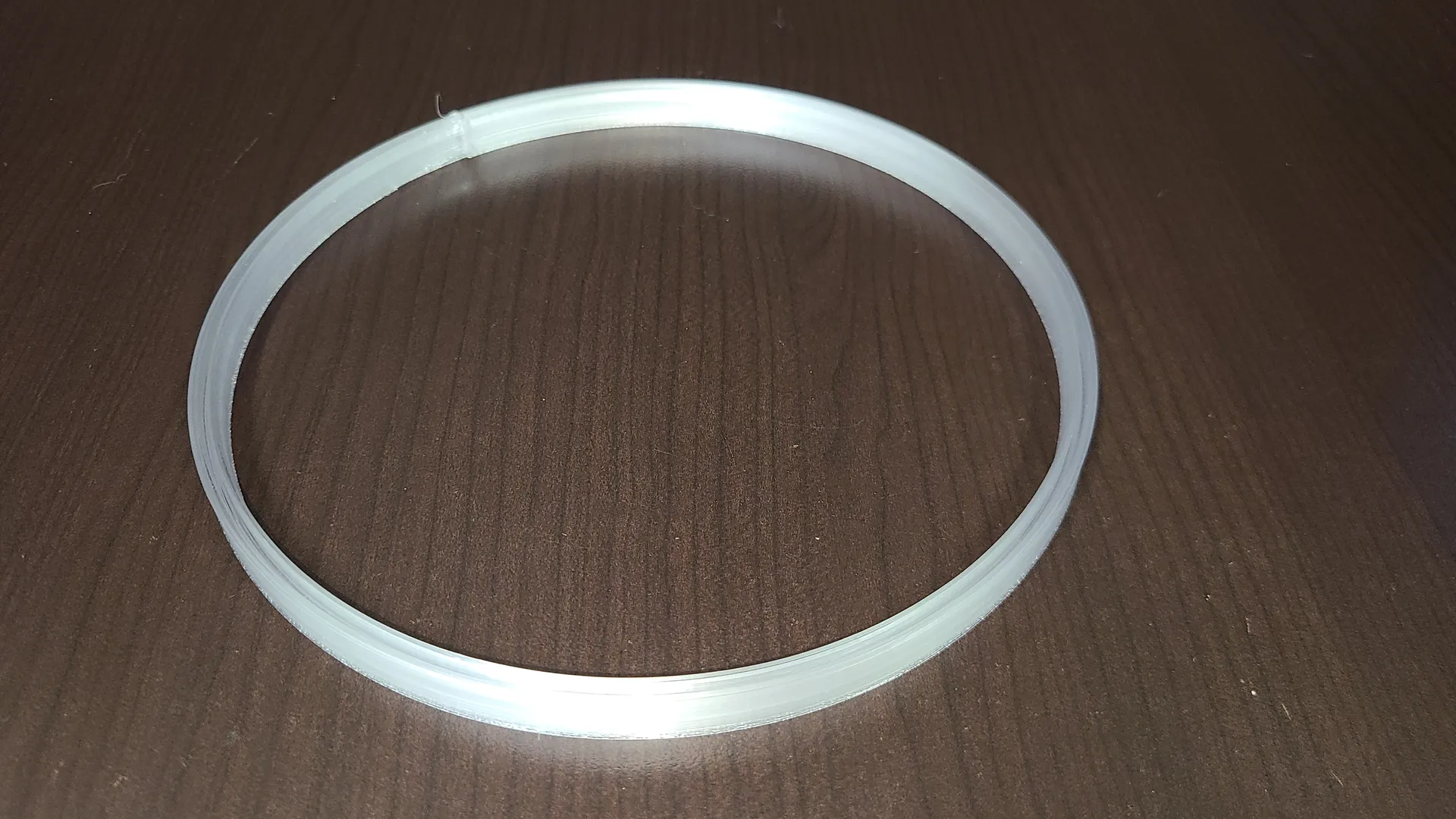
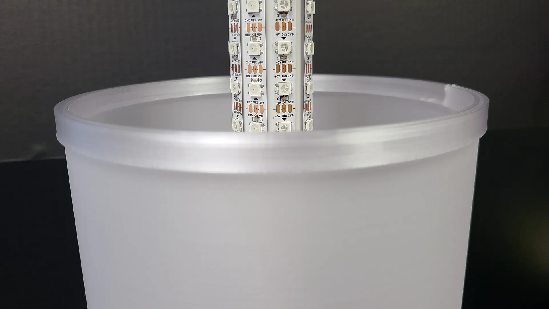
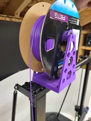
Diffusors are PetG…printed in VASE MODE, with a BRIM, using a 1mm nozzle and whatever speed gives you your desired opacity. I did 35mm and got very clear, so i increased to 45mm and got what you see. The diffusor model is 2mm wide. and the slot for the diffusors (base, connector and lid) are 2mm wide to accomodate elephant foot (from brim) and expansion. Do not use a smaller nozzle in vase, or the diffusor will be too thin and will move around. If your machine is smaller Z axis, resize in Z only.
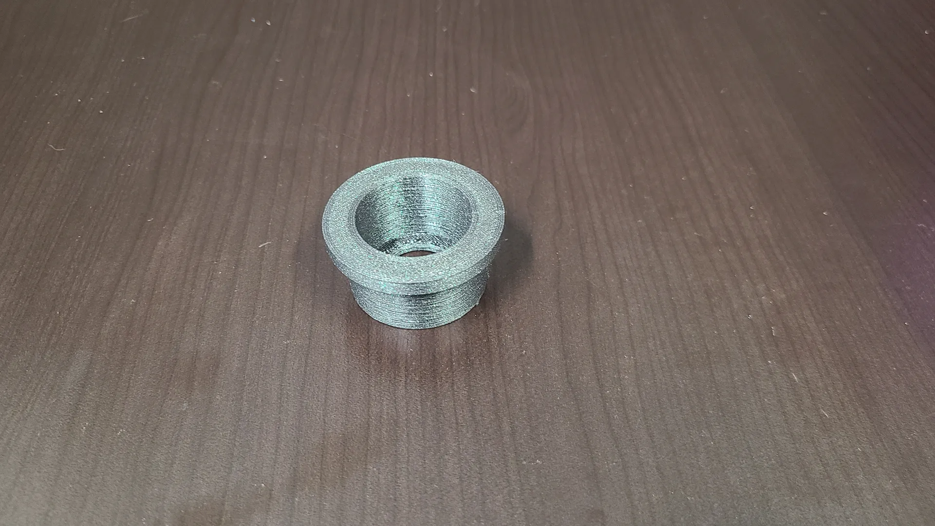
Diffusor connectors are PetG. I used the 1mm nozzle so it was already on, but i think a smaller nozzle would do better. 3 thinner walls may be stronger.
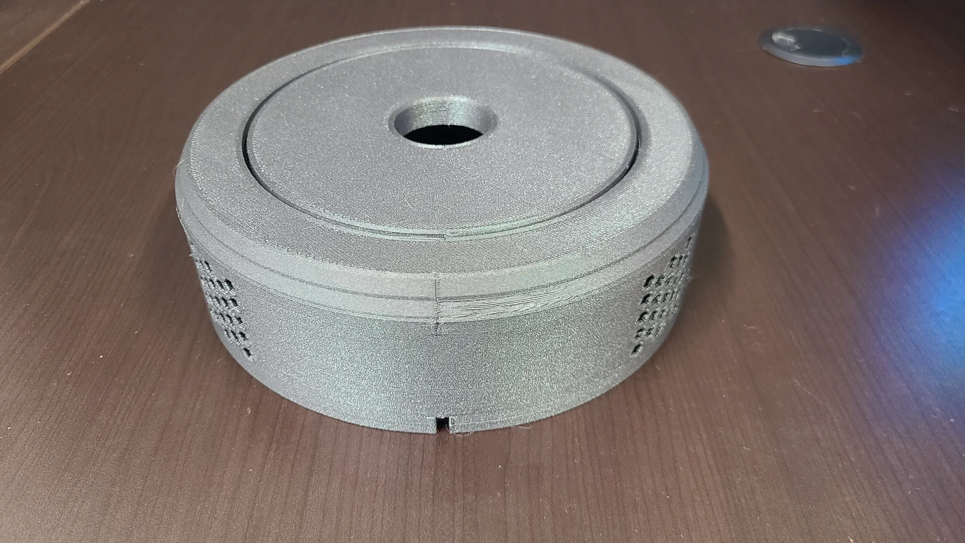
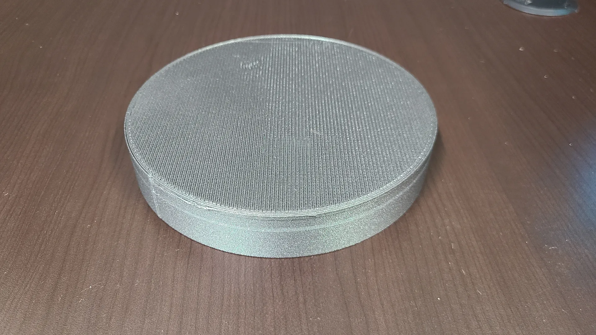
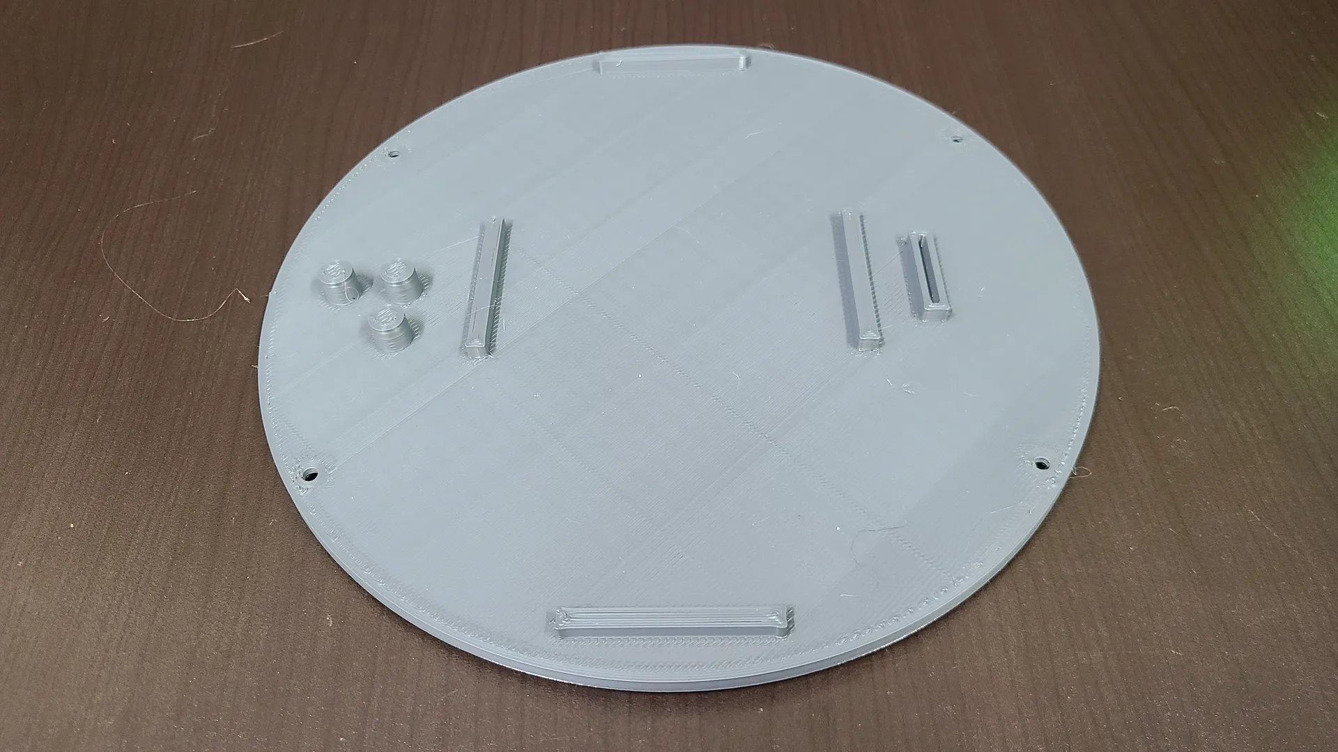
The rest of the pieces, Base, Base Cover, Lid, Column mount are in PLA. Use your own settings for these for speed and quality.
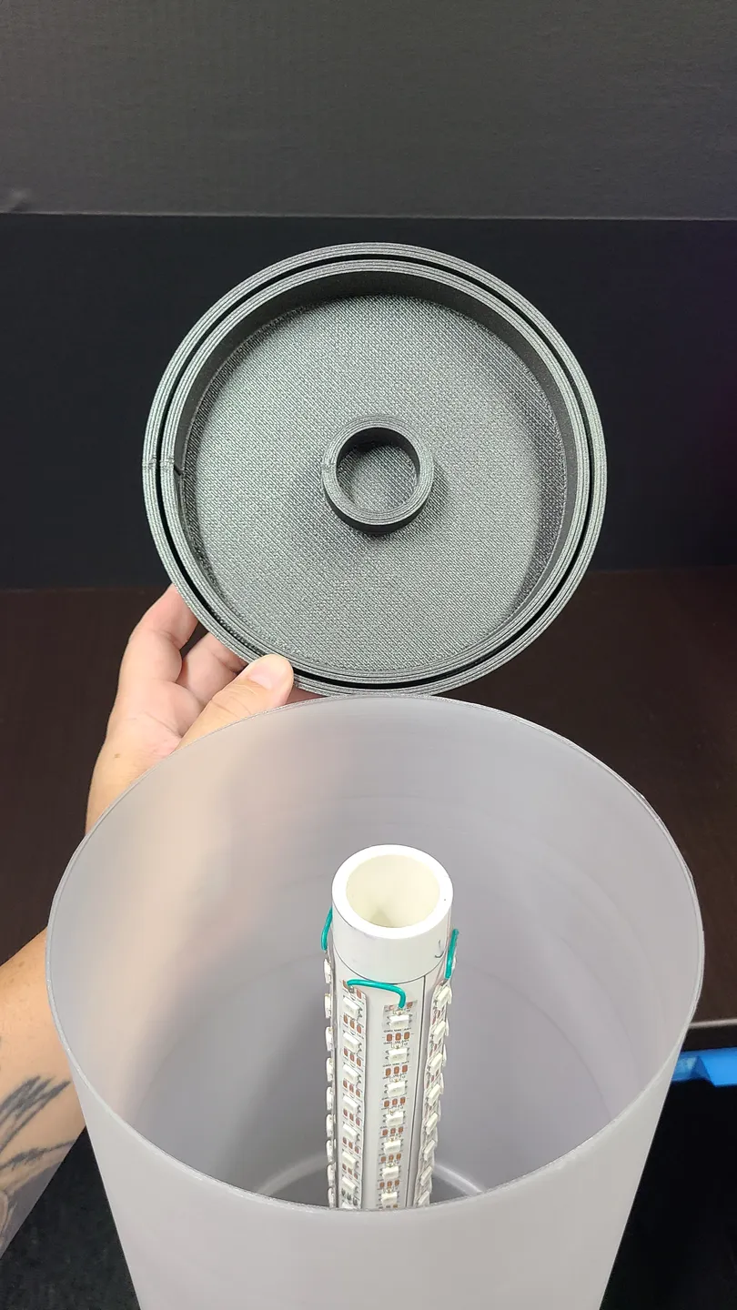
(1) 1.5'' PVC tube is required for the inner structure the led mount too. Sized to the height you will print (if you change it). 8 strips of led will surround the circumference of this tube. Plan the amount of LEDs you need accordingly.
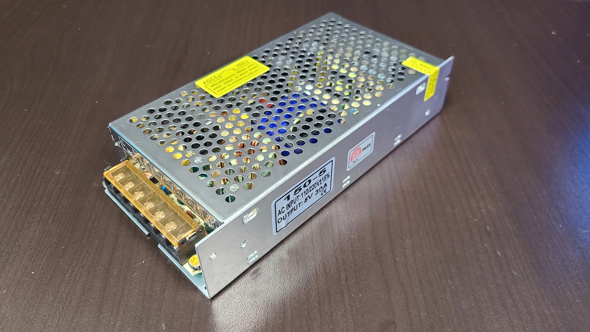
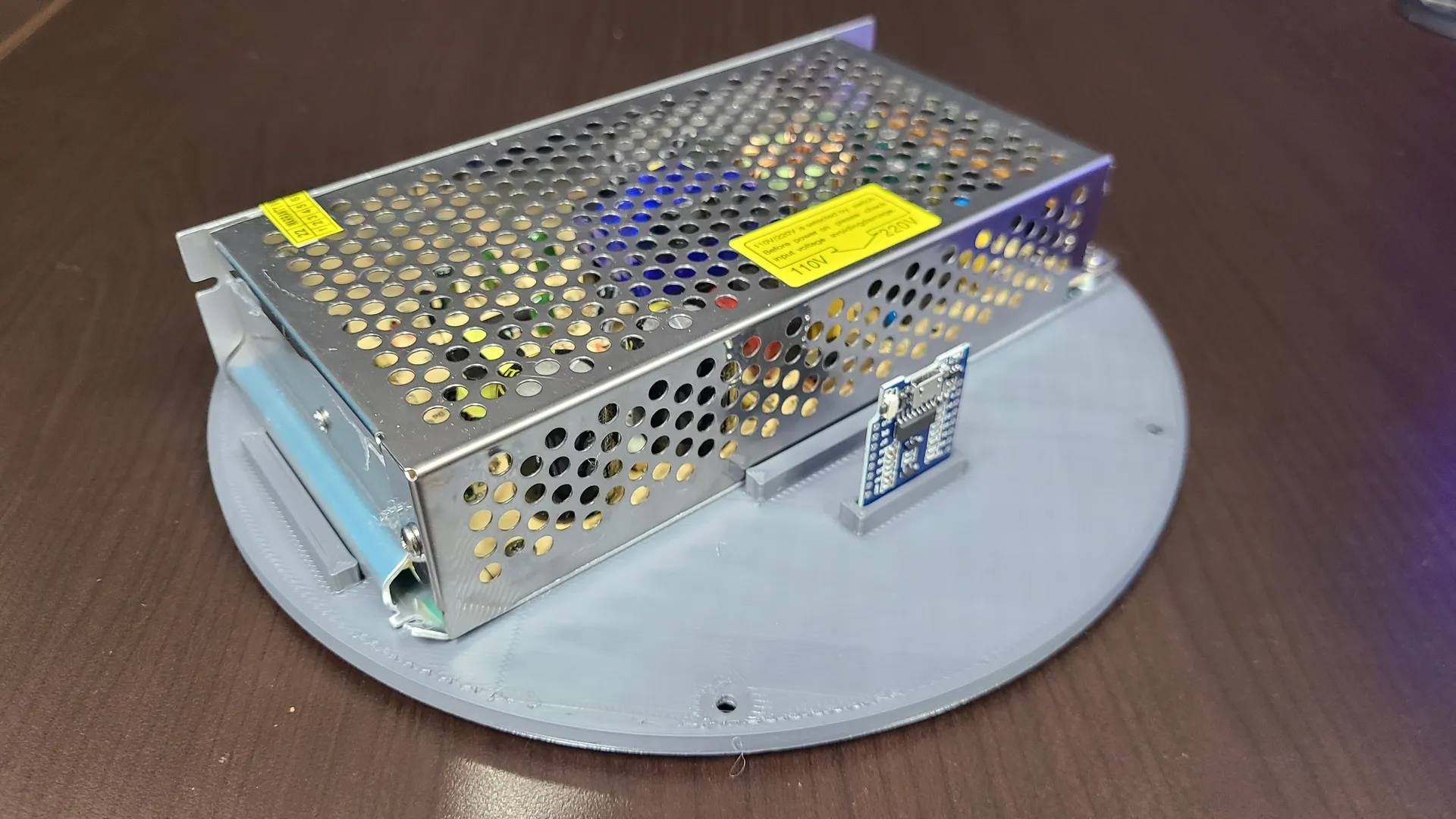
(1) Power supply will differ if you go bigger or shorter, but i used this one https://amzn.to/43uxf22 408led at 100% white pulls 25a. This PS is 30a, so that covers the 80% max duty recommended. The base cover has tabs to hold this particular PS in place along with using some gorilla glue double-sided tape (though other PS of less power are about the same size anyway)
(1) D1 Mini is required https://amzn.to/3pTGJpS . Other boards can be used, but you will have to custom fit it (base cover as slot specifically for D1)
WS2812B leds are required. https://amzn.to/3DcmR4y , buy enough for whatever height you end up printing.
Any old extension cord you have can be cut and tied into the power supply.
Assembly is quite straight forward. Print, test fit and set aside until all pieces are done.
Start with installing WLED into the D1 Mini.
https://install.wled.me/
Here is a good video if you've never done this.
After you install Wled to the D1 proceed with the next steps.
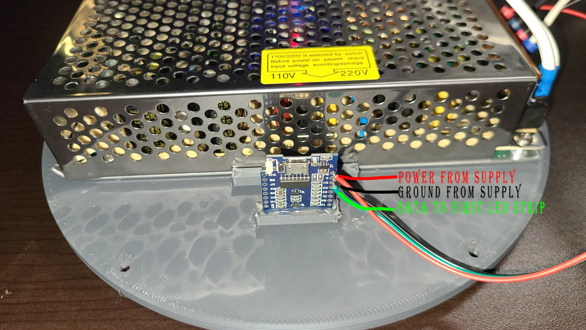
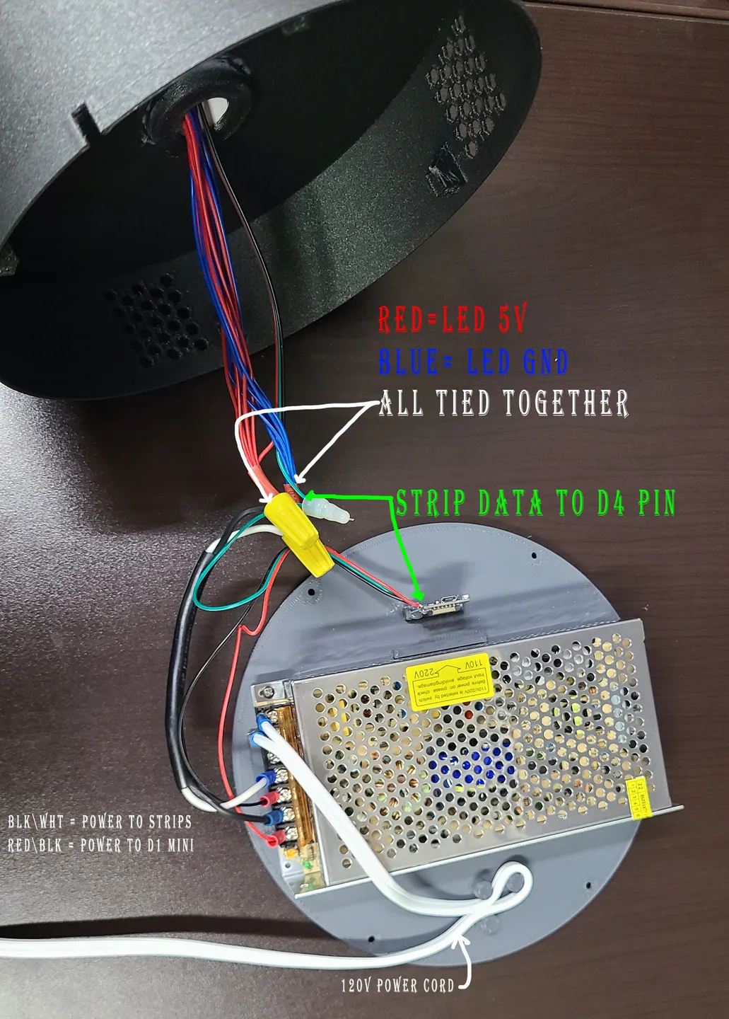
Install power supply to the base cover, i used double-sided tape). Solder 3 wires (red\grn\blk) to D1 mini in the 5V (red), GND (blk) , D4 pin (Green data). Seat the D1 into the slot (i used hot glue to keep in place) The 5v and Gnd wires connect to 1 set of V+\V- on the power supply, Leave the data wire for later.
Test fit all you diffusors and connectors together. Place in the base. Fit the PVC tube in the base and use a straight rule to mark the height to cut on the PVC tube. The LID has 15mm of travel where the diffusors sit, this gives some good grip on the pvc and diffusors so they don't move. Cut the PVC to fit.
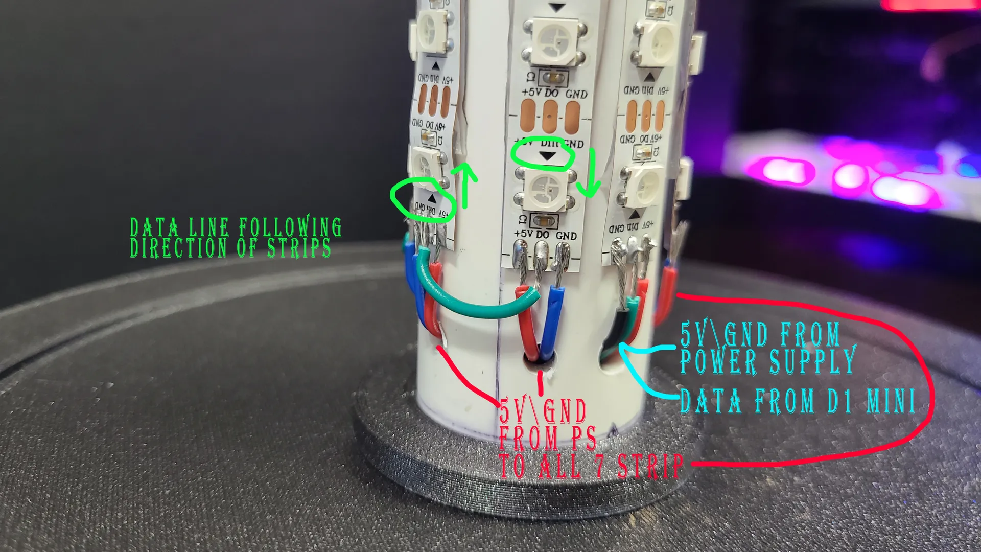
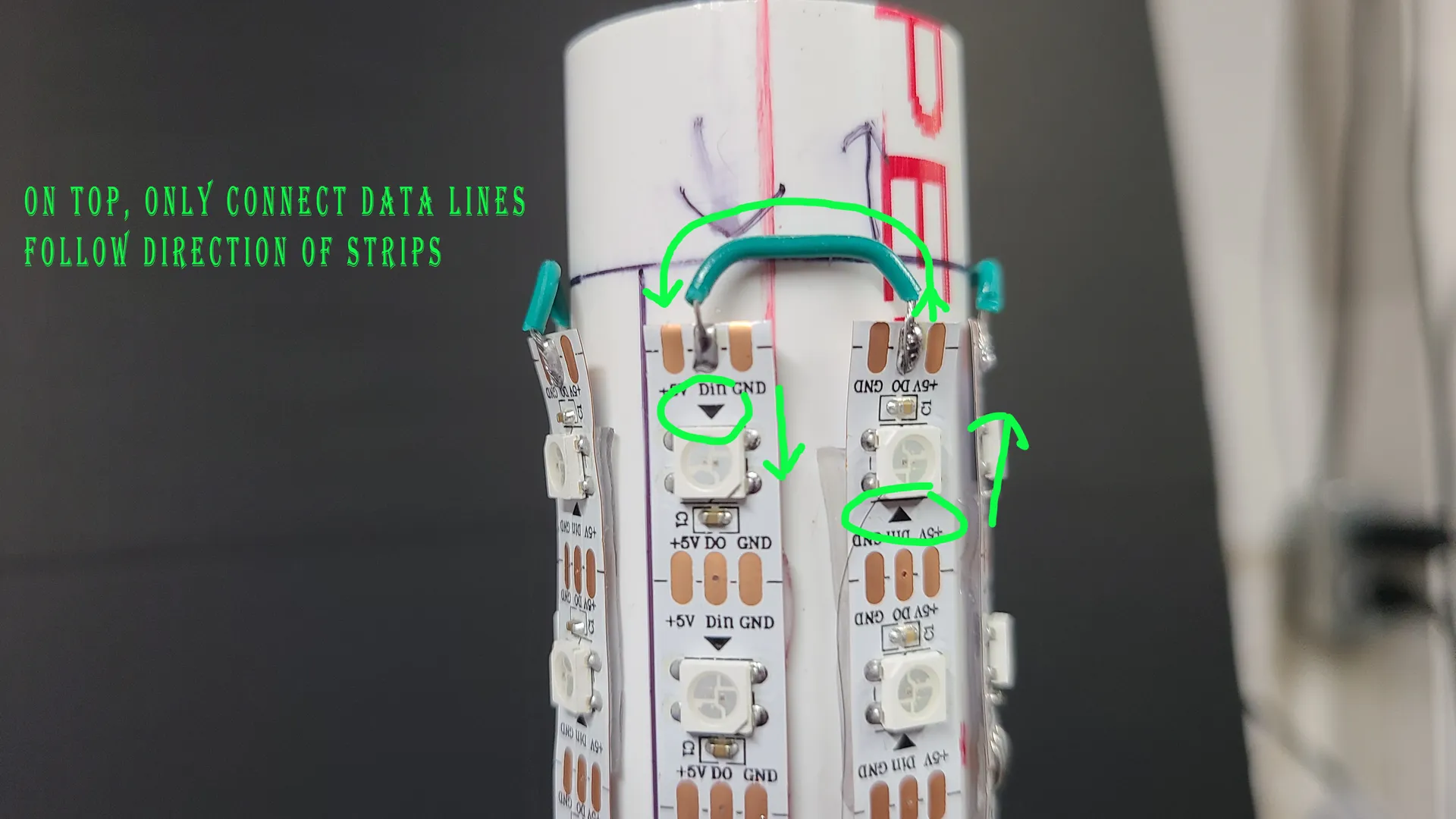
Now cut your LEDs so they're 4inches shorter than your PVC tube. This gives 2 inches to both ends for wiring. Lay out your strips and attach them to the PVC with about 4mm in between. PAY ATTENTION to the direction of the DATA of each strip (the little black arrows) One strip goes up, the next goes down..etc.
Now that all your strips are laid out. Drill 8 hole at the BOTTOM of the tube under each strip, to allow the wires through into the base. Choose a strip to be the FIRST in the series, this have the DATA wire soldered to it from the D1 mini's D4 pin, along with 5v\Gnd wires from power supply. (see photos). The remaining strips only get 5v\Gnd wire soldered and run into the hole. Once you have all 7 5v\gnd wires soldered and run into their holes (and the 5v\data\gnd for the first strip) it's time to run the DATA.
Find your FIRST strip (with 5v\gnd\data) and go to the top of this strip. You will solder a DATA wire on the DATA pin from this strip to the next strip (next strip should have an arrow pointing DOWN). Next follow the arrows and solder a DATA wire to each strip according to their direction. The last strip goes nowhere, it's the end of the line.
Once all your wires are soldered, insert the COLUMN MOUNT into the BASE. I glued these together for added support (even though it was a snug fit). Insert the PVC tube bottom into the tube, routing the wires through.
Now it's time to bundle up the LED strip wires. Tie all the 5v together then all the gnd together (see photo) Add one length of wire to each, to connect to the power supply, the other open set of V+\V- The DATA wire from the strips connects to the DATA wire coming from the D1 mini. Use the 120v extension cable you have, cut the female end off of it, strip the wires and connect them to the Load and Neutral on the power supply. There are 3 posts on the base cover, these are there to wrap the power cord around to prevent pulling the cord out of the base. (see photo)
With everything secured and tied up, test your setup and make sure all led strips light up. Default setup for WLED is only like 30leds or so. Go into WLED and set to the amount you have.
Once all LED are on and tested, route the wires so they fit inside the base and you can close the cover to the base. Use 4 small screws to secure the cover.
Now, install each diffusor your printed with a connector. Then put the lid on the top and you're all set to go.
I suggest, learn how to setup “segments” in WLED so you can tell WLED that each strip is it's own and then use “reverse direction” on the odd numbers strips, so they all work from the bottom up (instead of in series which would be bottom to top , then top to bottom on the next strip)
Tags
Model origin
The author marked this model as their own original creation.
