Hotend NeoPixel mod for Artillery Genius
Description
PDFI like that the Artillery printers come with an RGB LED on the hotend. It's a nice touch! But what if it could be... Brighter? And more rainbow-y???
Since I was digging into the case anyway to swap out my BLTouch probe for the stock inductive Z sensor per 3DPrintBeginner's excellent how-to, I decided to go ahead and also swap the stock RGB LEDs for a small NeoPixel strip. NeoPixels have a more elegant connector interface consisting of just three wires—5V/Signal/GND—compared to the typical 4-wire GND/R/G/B LEDs. This frees up more pins for activities!
In principle, it also means that you could add BOTH the inductive Z probe AND NeoPixel LEDs to the hotend of the Sidewinder X1 using only the 4-pin LED connector.
Here's how I did it:
NEOPIXEL WIRING
I used some individual NeoPixel boards I had laying around. (You can also get them in strips, which would be much more convenient.) For mine, I needed to solder together all the +5V pads, all the GND pads, and then connect each I/O OUT pad to the I/O IN pad on the subsequent NeoPixel. I used little bit of solid copper wire that I pre-tinned. If you have some insulated magnet wire, it would be a lot easier to just scrape of a bit of insulation over the pads and solder them that way. Finally, I solder on a 3-wire tail, terminating in a 3-pin male Dupont connector.
NEOPIXEL MOUNT
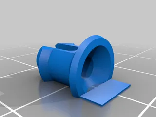
For the mount, I quickly printed it out of PETG, pressed the NeoPixels in, and soldered them together. The warm board stick will into the mount, but to be extra safe a slathered the back with some hot glue.
HOTEND WIRING
Because I have the Genius, which has breakout pins for the BLTouch right on the top, I made a little extension for the inductive sensor and plugged it in to the B/R/Y pins of that header. These correspond to GND/5V/Control for the BLTouch servo, and so it's important that the inductive sensor be connected appropriately. In my case, that meant connecting Blue/Brown/Black, respectively.
For the NeoPixels, I connected them to the R/G/B pins of the LED header, mosly so I could easily use the 3-pin header in the case directly.
MOTHERBOARD WIRING
Inductive Probe
Because the GND (B) and 5V (R) pins on the Genius hotend header have their own connections to power, you only need to worry about relocating the wire that was connecting the BLTouch header to the servo control pin. On my board, that was a single white wire ending in a Dupont connector, that was connected to pin D11 in the SERVOS1 header. You can see it plugged in just under the brown 3-wire LED connector in 3DPrintBeginner's photo here.
I moved this white wire over to pin D18 on the Z- endstop connector.
NeoPixels
For the NeoPixels, I repurposed that 3-wire brown LED connector that was originally plugged into the D4/D5/D6 digitial I/O pins. To keep things clean, I made up a little JST-to-Dupont dongle. I made sure the pins were connected SIG/5V/GND to the NeoPixels, and plugged it into the D5/5V/GND pins of the SERVOS2 header.
Filament Runout
This is very particular to my machine, but because I swapped out the stock TFT for a BigTreeTech TFT, I no longer had my filament runout sensor connected. So I went ahead and made another JST-to-Dupont dongle, and connected the 3-white-wire filament runout connector the D4/5V/GND pins of the SERVOS2 connector.
FIRMWARE CHANGES
My firmware is full of all sorts of randomness, so I won't post it here. But here's what you need to change on 3DPrintBeginner's firmware for the inductive Z probe mod to enable the NeoPixels:
COMMENT OUT:
define RGB_LED
UNCOMMENT:
define NEOPIXEL_STARTUP_TEST
define NEOPIXEL_LED
SET:
define NEOPIXEL_PIN 5
define NEOPIXEL_PIXELS 4
On mine, I also uncommented #define NEOPIXEL_IS_SEQUENTIAL for MAXIMUM RAINBOW, but if you want to have them all change color together, you can leave that commented out.
Finally, depending on the exact NeoPixels you're using, you might need to change #define NEOPIXEL_TYPE.
Sidewinder X1 Considerations
You should be able to use this as a starting point to add both the inductive Z probe and the neoPixels to the stock Sidewinder X1, using just the RGB LED header on the hotend.
To do this, you'll need to dedicate two of the R/G/B pins to the probe and NeoPixel I/O, the other to 5V for both, and also split the GND pin for both. Then, on the motherboard side, you would need to split the 3-pin brown wire harness up to have 1 pin connect to 5V and the other two to the appropriate digital IO pins. GND should be handled in the ribbon connector.
Print instructions
Category: 3D Printer Accessories Summary
I like that the Artillery printers come with an RGB LED on the hotend. It's a nice touch! But what if it could be... Brighter? And more rainbow-y???
Since I was digging into the case anyway to swap out my BLTouch probe for the stock inductive Z sensor per 3DPrintBeginner's excellent how-to, I decided to go ahead and also swap the stock RGB LEDs for a small NeoPixel strip. NeoPixels have a more elegant connector interface consisting of just three wires—5V/Signal/GND—compared to the typical 4-wire GND/R/G/B LEDs. This frees up more pins for activities!
In principle, it also means that you could add BOTH the inductive Z probe AND NeoPixel LEDs to the hotend of the Sidewinder X1 using only the 4-pin LED connector.
Here's how I did it:
NEOPIXEL WIRING
I used some individual NeoPixel boards I had laying around. (You can also get them in strips, which would be much more convenient.) For mine, I needed to solder together all the +5V pads, all the GND pads, and then connect each I/O OUT pad to the I/O IN pad on the subsequent NeoPixel. I used little bit of solid copper wire that I pre-tinned. If you have some insulated magnet wire, it would be a lot easier to just scrape of a bit of insulation over the pads and solder them that way. Finally, I solder on a 3-wire tail, terminating in a 3-pin male Dupont connector.
NEOPIXEL MOUNT
For the mount, I quickly printed it out of PETG, pressed the NeoPixels in, and soldered them together. The warm board stick will into the mount, but to be extra safe a slathered the back with some hot glue.
HOTEND WIRING
Because I have the Genius, which has breakout pins for the BLTouch right on the top, I made a little extension for the inductive sensor and plugged it in to the B/R/Y pins of that header. These correspond to GND/5V/Control for the BLTouch servo, and so it's important that the inductive sensor be connected appropriately. In my case, that meant connecting Blue/Brown/Black, respectively.
For the NeoPixels, I connected them to the R/G/B pins of the LED header, mosly so I could easily use the 3-pin header in the case directly.
MOTHERBOARD WIRING
Inductive Probe
Because the GND (B) and 5V (R) pins on the Genius hotend header have their own connections to power, you only need to worry about relocating the wire that was connecting the BLTouch header to the servo control pin. On my board, that was a single white wire ending in a Dupont connector, that was connected to pin D11 in the SERVOS1 header. You can see it plugged in just under the brown 3-wire LED connector in 3DPrintBeginner's photo here.
I moved this white wire over to pin D18 on the Z- endstop connector.
NeoPixels
For the NeoPixels, I repurposed that 3-wire brown LED connector that was originally plugged into the D4/D5/D6 digitial I/O pins. To keep things clean, I made up a little JST-to-Dupont dongle. I made sure the pins were connected SIG/5V/GND to the NeoPixels, and plugged it into the D5/5V/GND pins of the SERVOS2 header.
Filament Runout
This is very particular to my machine, but because I swapped out the stock TFT for a BigTreeTech TFT, I no longer had my filament runout sensor connected. So I went ahead and made another JST-to-Dupont dongle, and connected the 3-white-wire filament runout connector the D4/5V/GND pins of the SERVOS2 connector.
FIRMWARE CHANGES
My firmware is full of all sorts of randomness, so I won't post it here. But here's what you need to change on 3DPrintBeginner's firmware for the inductive Z probe mod to enable the NeoPixels:
COMMENT OUT:
define RGB_LED
UNCOMMENT:
define NEOPIXEL_STARTUP_TEST
define NEOPIXEL_LED
SET:
define NEOPIXEL_PIN 5
define NEOPIXEL_PIXELS 4
On mine, I also uncommented #define NEOPIXEL_IS_SEQUENTIAL for MAXIMUM RAINBOW, but if you want to have them all change color together, you can leave that commented out.
Finally, depending on the exact NeoPixels you're using, you might need to change #define NEOPIXEL_TYPE.
Sidewinder X1 Considerations
You should be able to use this as a starting point to add both the inductive Z probe and the neoPixels to the stock Sidewinder X1, using just the RGB LED header on the hotend.
To do this, you'll need to dedicate two of the R/G/B pins to the probe and NeoPixel I/O, the other to 5V for both, and also split the GND pin for both. Then, on the motherboard side, you would need to split the 3-pin brown wire harness up to have 1 pin connect to 5V and the other two to the appropriate digital IO pins. GND should be handled in the ribbon connector.
Tags
Model origin
The author marked this model as their own original creation. Imported from Thingiverse.


