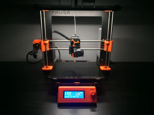
LED Light Bar Prusa MK4

Description
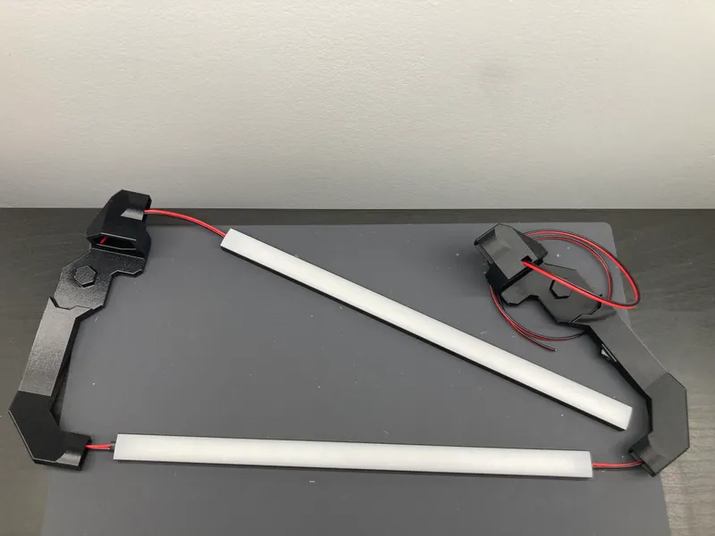
PDFLight bar for the Prusa MK4 available in single and dual light versions. Mounts are designed to fit 9x17mm aluminum u-channel and have a hollow interior that is used to route the wires down the back of the printer frame for a clean look. Mounts also include an opening to insert a power switch. The LED strips can be powered by the printer power supply. Uses standard 24V LED strips.
Thanks to all who helped me test fitment! If you have any suggestions for improvement, please let me know.
See below for assembly instructions.
This is the MK4 version. Click below for other light bar versions.
MK2/MK3 Dual Light
MK2/MK3 Dual MMU2 Light
MK2/MK3 Single Light
MK2/MK3 Bear Upgrade
MK3 Side Light Bar
MINI Light Bar
I have partnered with VOXELPLA to offer the MK4 Light Bar as kits and pre-assembled light bars. Visit the VOXELPLA Store for more info.

Files:
MK4 Hex Z-Axis Top: Since there is no mounting point on the stock MK4 z-axis tops, I modified them to add a hexagonal hole that the light bar can mount to. These will replace the stock z-axis tops on your printer. No supports required.
MK4 Dual Mount: Standard dual light version that attaches to the hexagonal holes in the modified z-axis tops. Supports required for rear overhang and protruding hexagonal peg.
MK4 Single Mount: Standard single light version that attaches to the hexagonal holes in the modified z-axis tops. Supports required for protruding hexagonal peg.
MK4 Dual Mount - Z-Axis Top: Dual light version that integrates the Prusa z-axis top pieces into the light bar for a more sturdy mount. Remove the stock z-axis tops and replace with this light bar mount. No supports required.
MK4 Single Mount - Z-Axis Top: Single light version that integrates the Prusa z-axis top pieces into the light bar for a more sturdy mount. Remove the stock z-axis tops and replace with this light bar mount. No supports required.
Print instructions
Recommended Print Settings:
Print Settings: 0.20mm QUALITY
Layer Height: 0.20mm
Infill: 15% Gyroid
Supports: Build plate only
Open 3MF files in PrusaSlicer for preconfigured settings
Required hardware:
Aluminum u-channel (9x17mm)
24V LED strip
Wire
Power switch (KCD11 10x15mm)
Heat shrink tubing
Fork terminals
Replacement zip tie
Hardware Kit
Purchase a hardware kit from VOXELPLA.com at the link above.
Tools:
Wire stripper
Soldering tools
Hacksaw
2mm Hex key
Wire crimper
Metal file (optional)
Assembly Instructions
Pictures shown are for the dual light version. The single light version instructions are basically the same, just without the additional LED strip.
If you purchased a pre-assembled kit, scroll to the bottom for instructions on how to install and connect to power.
Cut Material to Length
If you purchased a hardware kit you can skip these steps as all material comes cut to the correct length.
1. Cut the u-channel to 31cm and and check that it slides into the mount ends. Use a metal file to round off any sharp edges to make it slide in easier.
2. Cut the LED strip at the designated cutting areas to fit the u-channel.
3. Cut the red and black wire to 90cm (36").
4. For the dual light version, cut an additional 45cm (18") wire.
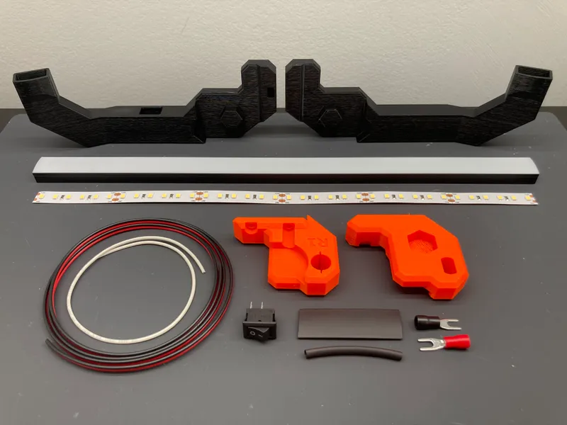
Single Light Kit
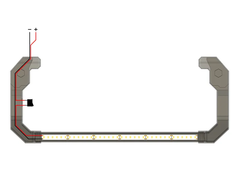
Single Light Wiring Diagram
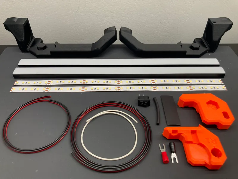
Dual Light Kit
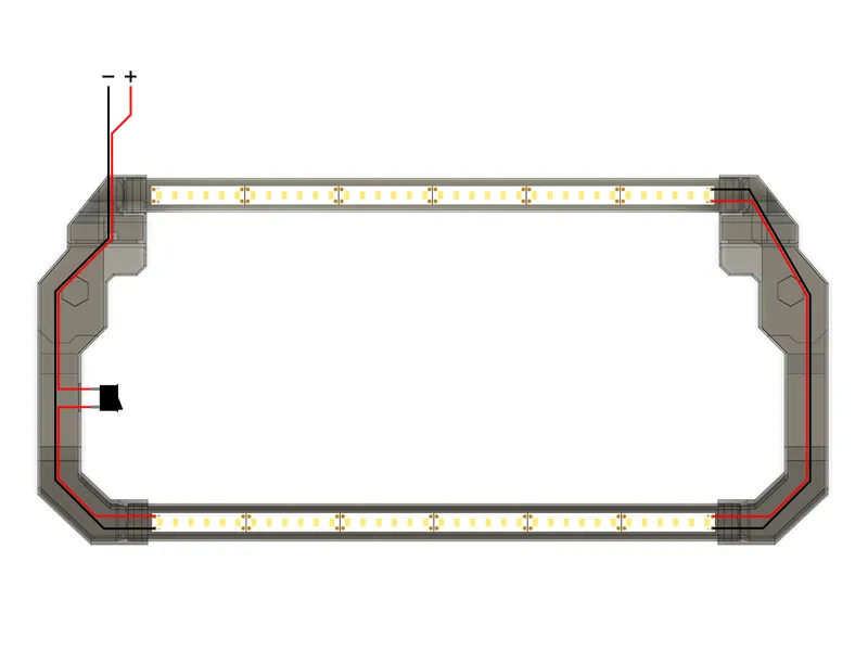
Dual Light Wiring Diagram
Inserting Wire
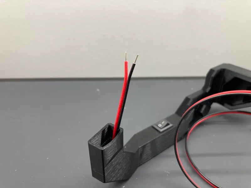
1. Insert the longer red and black wire into the left side mount through the small opening on the rear side and feed it up to and out of the switch hole. If you have trouble getting the wire through, feed through the white pull wire, strip the end and solder it to the red and black wire. Use that to pull the red and black wire through, then cut off the pull wire.
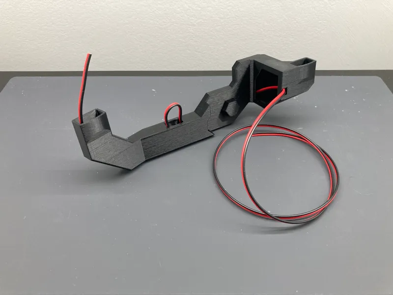
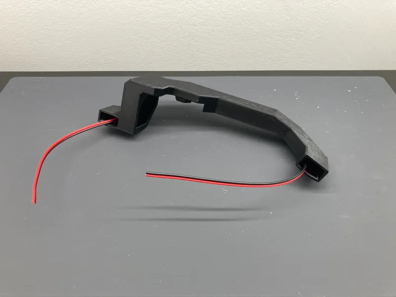
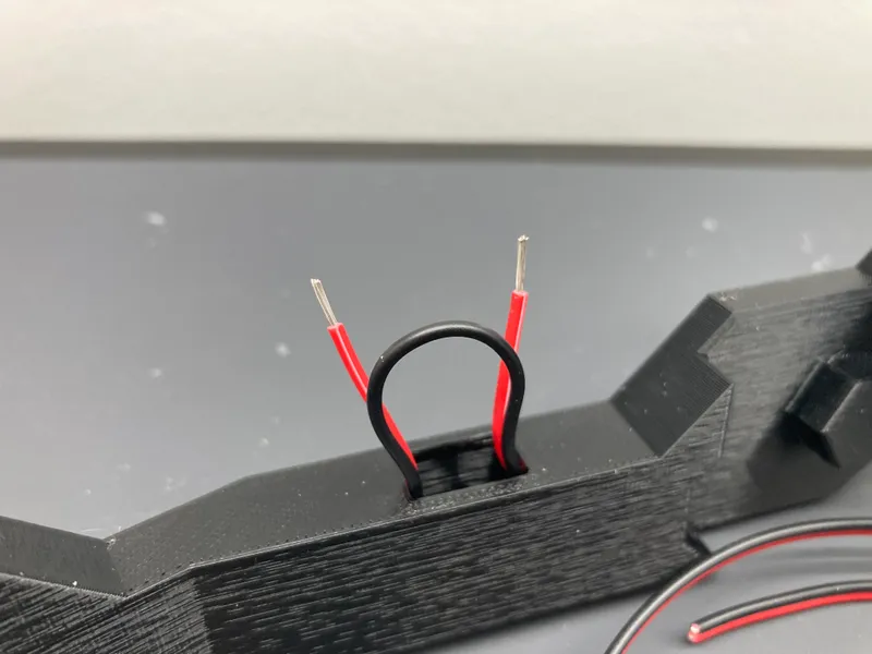
2. Loop the red and black wire back into the switch hole and out the front exit hole. Leave a small loop of wire sticking out the switch hole.
3. If making the dual light version, feed the shorter red and black wire through the right side mount.
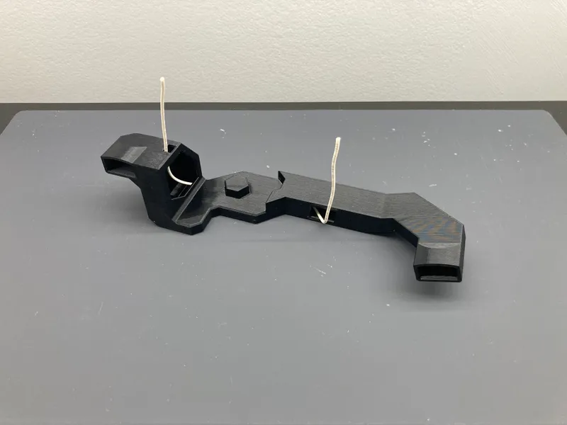
Optional pull wire
Left mount wire
Right mount wire
Power Switch Wiring
1. Cut the red wire for the power switch. Be careful when cutting not to also cut through the black wire insulation. Pull back the red wire and strip off the ends.
2. Place heat shrink over the wires and solder the power switch to the red wires. For best soldering results, tin the wires and switch terminals with solder first, then join together. Put the heat shrink in place and apply heat.
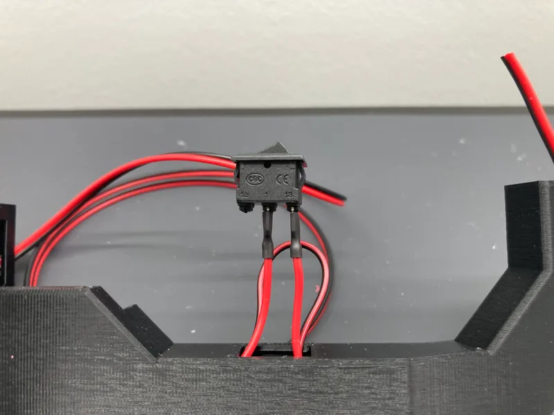
3. Insert the power switch into the opening. Pull the wire on either end to remove any slack. The power switch needs to be 10x15mm to fit in the provided opening.
Cut wire for switch
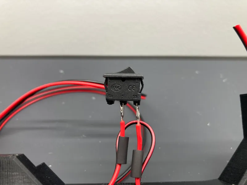
Solder switch
Heat shrink
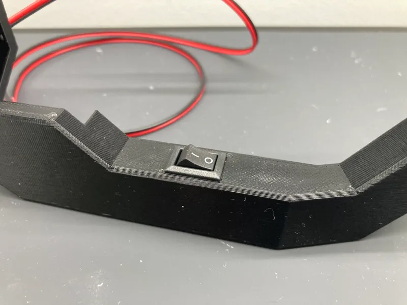
Insert switch
LED Strip Wiring
1. Cut the wire so that there is about 5cm (2") sticking out the mount opening and strip about 5mm (¼") off the ends of the wires.
2. Solder the wires to the LED strip, red to + and black to -. For best soldering results, tin the LED pads and wires with solder first and then join them together. Put the heat shrink in place and apply heat.
3. IMPORTANT: Make sure that the solder/wires are NOT touching the solder joints on the individual LED chip closest to the end and are only touching the designated solder pads on the strip. If the wire is touching the solder joints on the LED chip, once power is applied this could blow that single LED chip causing the segment on the end of the strip to stop working.
4. If making the single light version, skip to step 9.
5. For the dual light version, put another piece of heat shrink around the front LED strip. Strip the ends of the shorter wire and solder to the other end of the front LED strip, red to + and black to -. Put the heat shrink in place and apply heat.
6. Feed the shorter red and black wire through the right side mount if not done already. Make sure the right side mount is in the correct orientation.
7. Trim the shorter wire so there is 2-5cm (1-2") sticking out both ends of the right side mount.
8. Strip 5mm (¼") off the other end of the wires and solder to the rear LED strip, red to + and black to -. Put the heat shrink in place and apply heat.
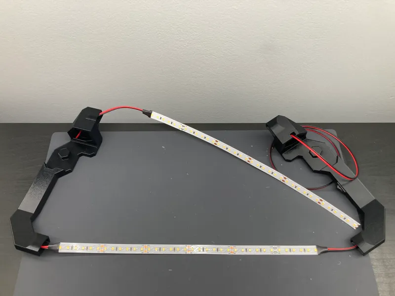
9. Remove the adhesive backing from the front and rear LED strips and stick them to the inside of the u-channel.
10. Attach the frosted cover to the u-channel and insert into the mounts. Fold the wire for easier insertion. Use the cavity near the rear opening to bundle the wire slack on the right side mount.
Strip LED wire
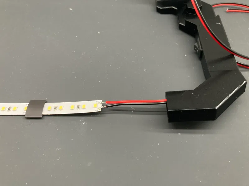
Solder LED strip
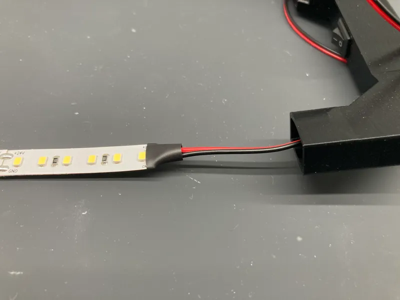
Installed LED strip
Completed soldering
Installed u-channels
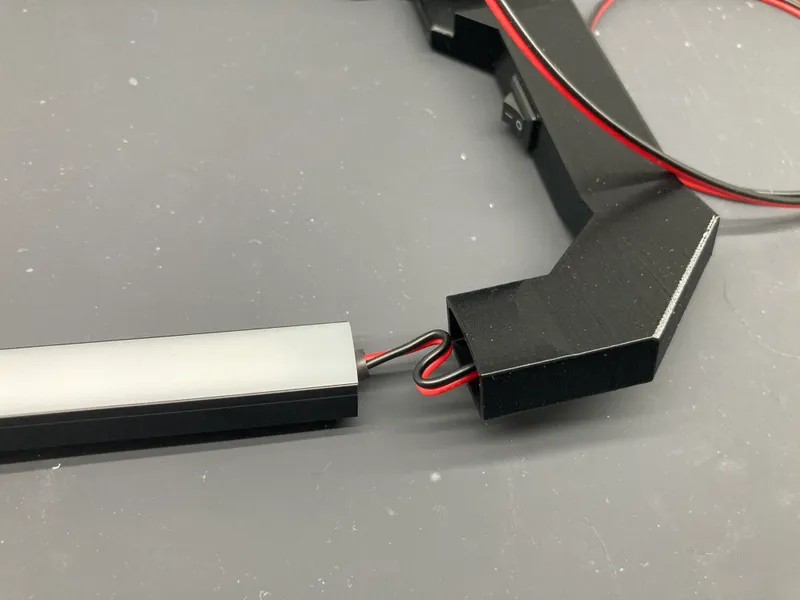
Fold wire and insert u-channel
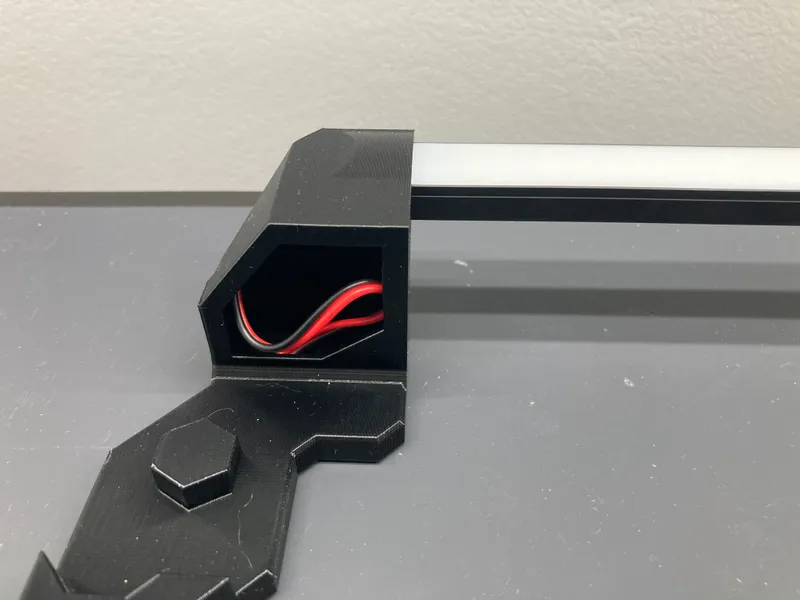
Bundle wire slack
Final Assembly
1. Remove the stock z-axis top pieces from the printer.
2. Install the modified z-axis top pieces with the hexagonal hole.
3. Locate the extruder cable bundle holder on top of the electronics box. On the side closest to the printer frame you will see some angled notches in the printed piece. These pieces are meant to be broken away to open a passageway for wires into the electronics box.
4. Undo the zip tie and screws holding the piece facing outward. Using a flat blade screwdriver or pliers, break off the triangular corner piece.
5. Install the light bar onto the printer and route the wire down the back of the frame and into the electronics box through the opening now available. Make a note of where to cut the red and black wire to connect to the power terminal screws on the control board. It should be around 16" from where the wire exits the light bar mount.
6. Cut the red and black wire to the length noted in the previous step and strip off the ends. Using a crimping tool, attach the fork terminals to the wires.
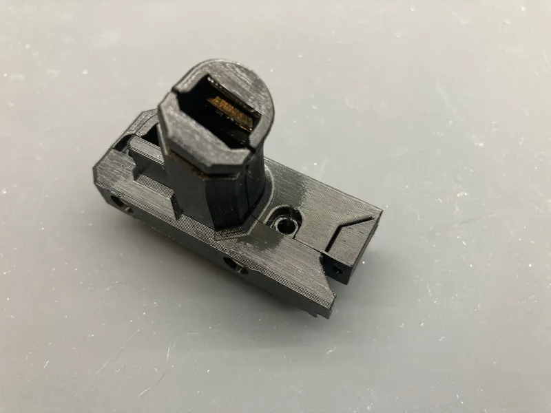
7. If you pulled the wire out of the opening to attach the fork terminals, reinsert it through the opening. Reinstall the screws and a new zip tie for the piece holding the extruder cable bundle. Make sure to not pinch any wires.
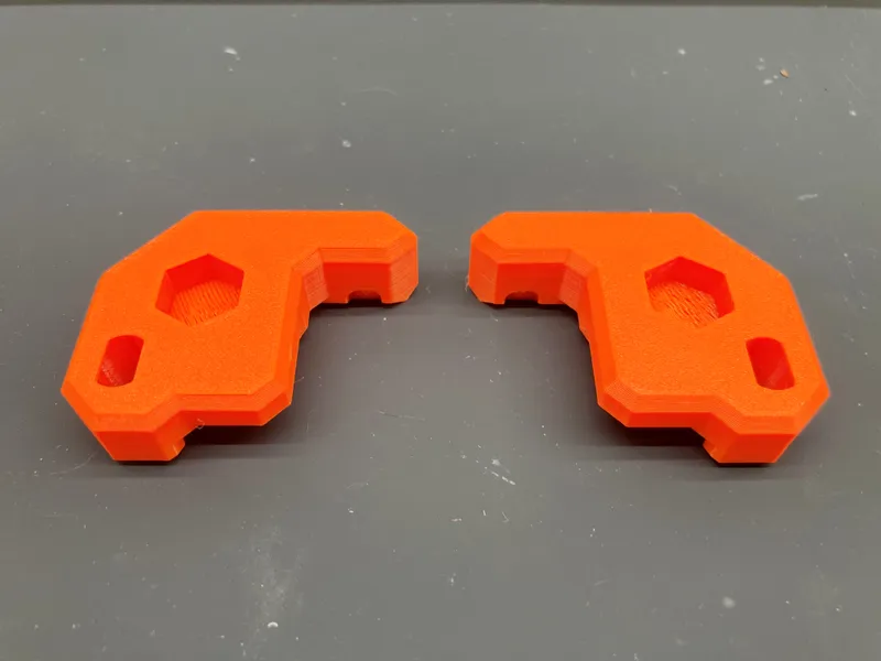
Modified z-axis tops
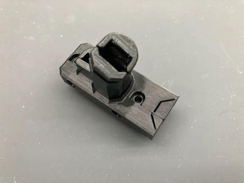
Cable bundle holder
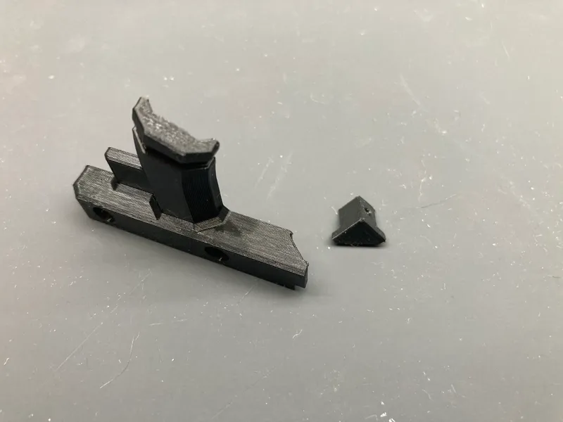
Break off corner
Wire run opening
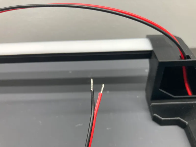
Strip power wires
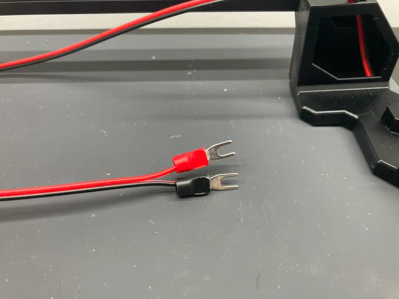
Fork terminals
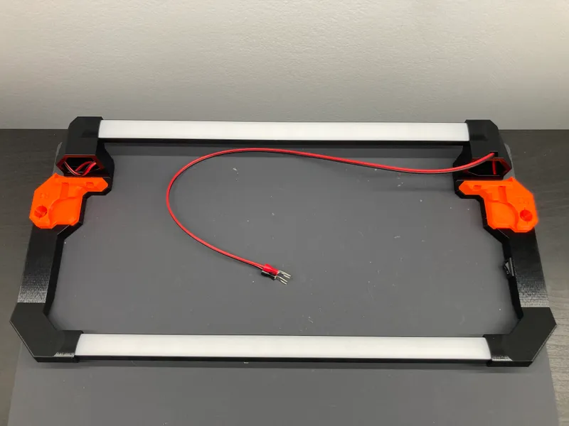
Completed assembly
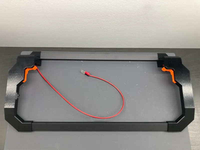
Completed assembly
Power Connection
To power the light bar with the MK4 printer power supply, connect the red and black wires to the screw terminals on the xBuddy board labeled POWER IN + and - . Red to + and black to - . Undo the screw terminals enough to insert the power and ground fork terminals and stack them with the wires coming from the printer power supply. Once in place, tighten the screw terminals. Tug gently on the wires to ensure that they are secure. The LED strips only consume 5W (single) and 10W (dual), so it won't put much excess load on the power supply.
Double check that the fork terminals and ring terminals are seated tightly and that the screw is tight. If needed, bend the fork terminals slightly so the plastic parts don't interfere with the connectors on the power supply wires.
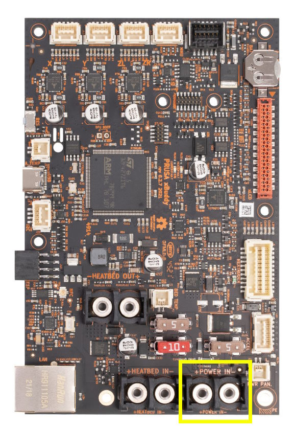
Power connection (+ Left, - Right) Photo Credit: Prusa Research
Tags
Model origin
The author marked this model as their own original creation.