40-10m 9:1 UNUN EFHW Antenna

Description
PDFPortable, pack style antenna. The parts to be printed are - Antenna matching circuit enclosure, loading coil bobbin, wire end insulator, and wire winder for an end fed half wave antenna.
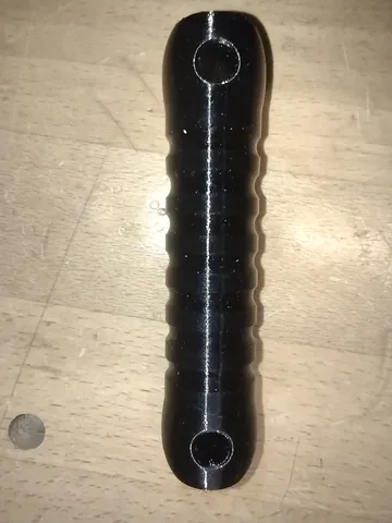
The shape of the UNUN enclosure is intended to reduce the overall footprint and minimize corners to protrude in a pack. The coil bobbin has a recessed winding area to minimize abrasion and catching on tree branches or other support structures it might be drawn across. The winder is intended to be slightly smaller and intended to have some aesthetic appeal - an integral design that could reduce the overall size is an idea for the future.
The impedance matching circuit is a 9:1 turn ratio transformer.
A loading coil is employed to reduce overall length and is a 34uH wound coil on a bobbin placed 34' from the feed point of the antenna.
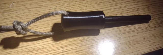
An antenna end insulator is employed to anchor the non-feed end of the antenna wire
A winder holds it all together for transport and storage
PETG may be a better option than PLA because of it's stretchiness, recommended it be used for the bobbin and insulator since they are under more tension. The winder could also benefit from a stretchier plastic to avoid breakage in a pack.
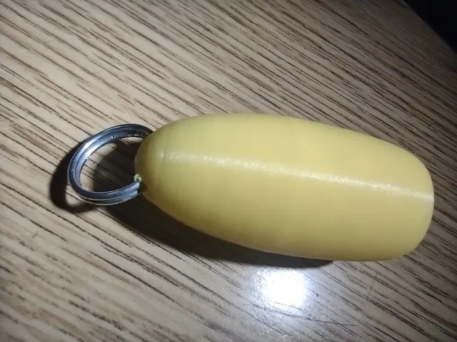
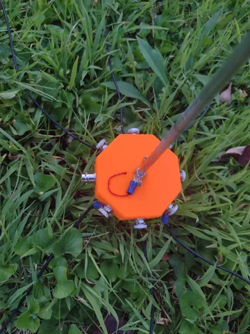
UNUN enclosure:
The center hole of the unun enclosure is sized for m4 threads and a tap can be used to cut the threads. A warmed screw may also be used. A 10mm length flush m4 screw fits well, stainless or other weatherproof material is recommended.
The eyebolt is an m4 threads size, I secured it with a nylock nut to prevent loosening.
The coax connector hole is sized for a panel mount bnc connector.
The antenna terminal hole is purposefully small to be sized for whatever terminal I have available on hand. Pomona banana plug style or screw type terminals usually work well. A step drill bit makes enlarging the hole to the desired size easy.
Matching transformer with a 3 turn primary and 27 turn secondary was used for this example. The ferrite used here is a size 82 composition 43 bead. A ~1m length of 24AWG magnet wire is used for the turns. ~15cm is folded back on itself and twisted to form the primary and first 3 secondary turns.
Load coil:
24AWG copper magnet wire wound the length between the two small holes located within the recessed area of the bobbin should provide a 33-34 uH inductor. Covering with electrical tape may aid in preventing unraveling and some weatherproofing. 30mm lengths extending from each end will provide sufficient lead length.
Wire portion:
40' overall, 34' from UNUN to load coil with a 6' length extending from the load coil to the end insulator. Adding an extra foot or two for tuning and attachment should be considered.
Tags
Model origin
The author marked this model as their own original creation.