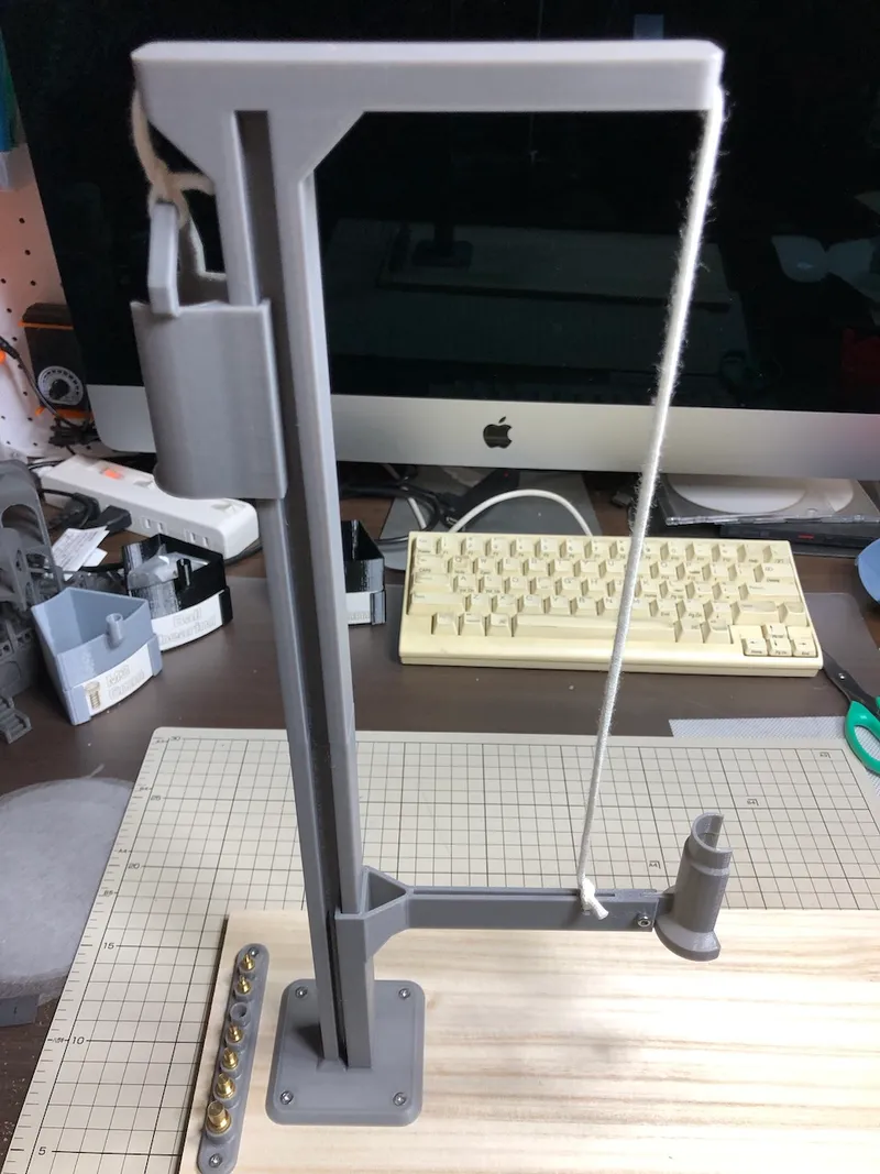
Heat Set Insert Press using H-Pillar

Description
PDFUpdate 5/28/2023
Added "arm 2.step" with additional projections to reduce wobble.
ぐらつきを減らすための突起を追加した"arm 2.step"を追加しました。
---------------------------------------------------------------------------------------------------------------
Parts used in previous models
従来のモデルで使われていた部品
A search for "heat set insert press" in Printables reveals numerous models registered. The machine parts used in them included the following
Printablesで「heat set insert press」を検索すると数多くのモデルが登録されていることがわかります。それらに使われている機械部品には以下のようなものがありました。
- Aluminum extrusion アルミ押し出し材
- Bearings, Linear ball bearings ベアリング、リニアボールベアリング
- Pulley 滑車
- Linear Rod リニアロッド
- Springs バネ
- Linear Guide リニアガイド
Parts used in this model
このモデルで使う部品
I thought it was a bit wasteful to use these parts for a tool that is used only occasionally, so I decided to design a tool that does not use them. This model does not use any of the above parts. All that is needed is the following
たまにしか使わない工具に使うには少々もったいないと思ったので、これらを使わない設計にしてみました。このモデルでは上記部品を一切使いません。必要なのは以下のものです。
- A board to be used as a base 土台として使う板
- String 紐
- Mounting screws and nuts 取り付け用のネジとナット
Parts to be printed
印刷する部品
Please print the following six parts. It is better to read the entire description before printing.
以下の六つの部品を印刷してください。説明を一通り読んでから印刷する方が良いでしょう。
- lower pillar
- upper pillar
- connector
- arm
- counter weight
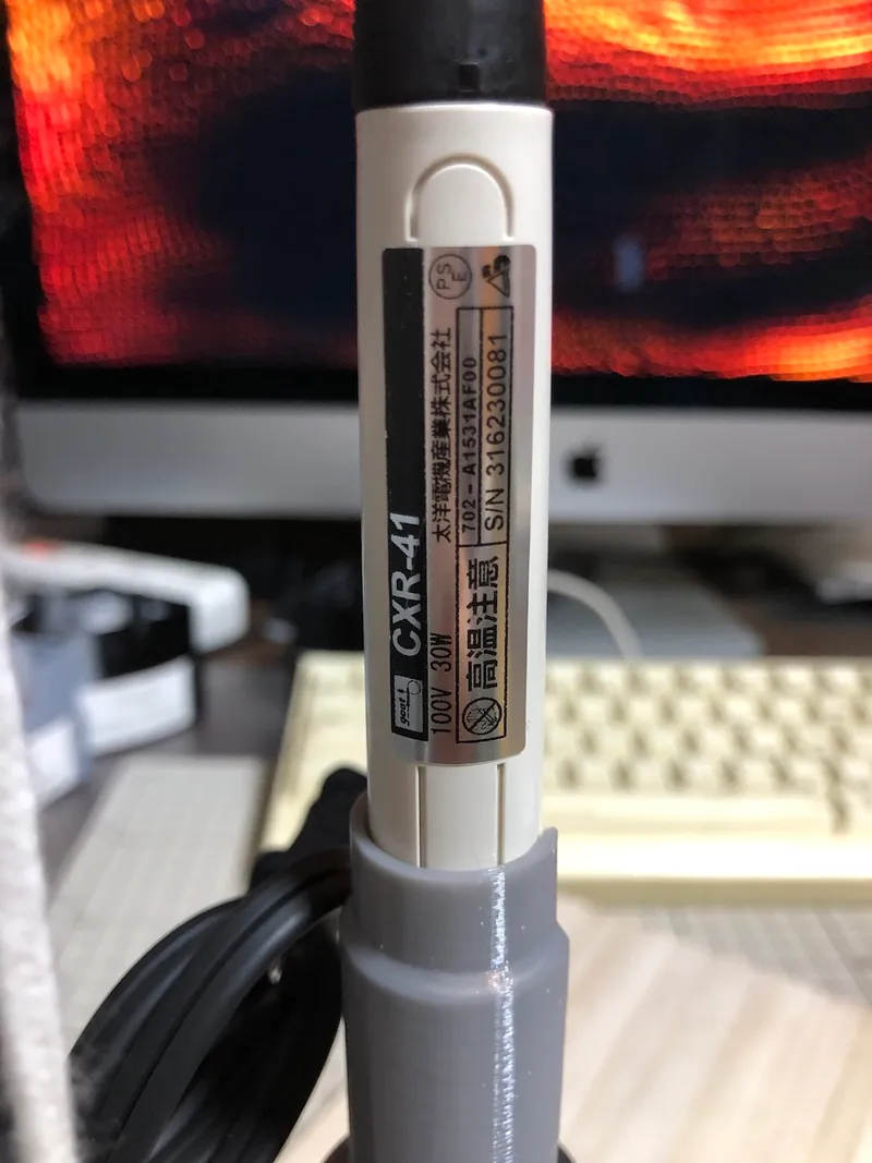
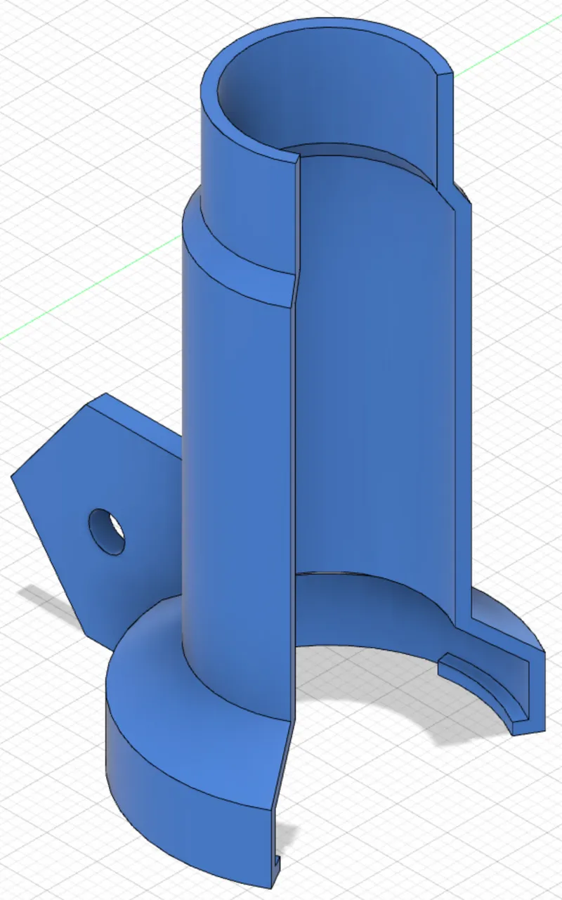
- iron holder goot CXR-41
However, the iron holder must be modified to fit the shape of your soldering iron.
ただしiron holderはあなたがお持ちのハンダゴテの形に合わせて修正する必要があります。
Use Fusion360 to modify the cross-sectional shape of the iron holder.
Fusion360を使ってiron holderの断面形状を修正してください。
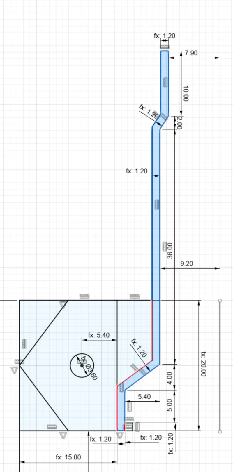
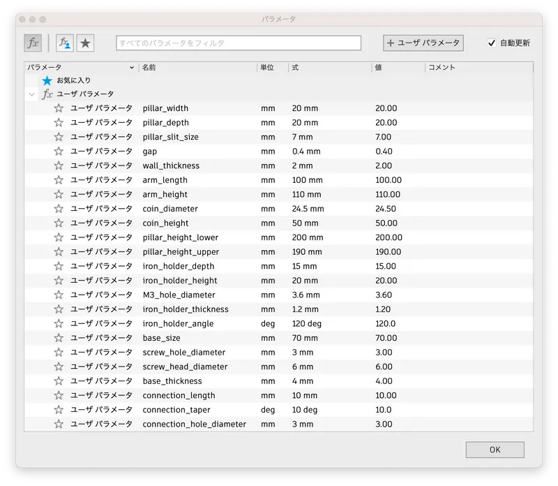
If the dimension value is not preceded by fx:, change the value directly; if it is preceded by fx:, modify the value of the parameter. The relevant parameters are
寸法の数値の前にfx: がついていないものは直接値を変更してください。fx: がついているものはパラメータの値を修正してください。関連するパラメータは以下のものです。
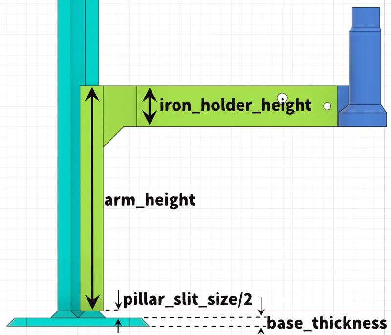
- iron_holder_height
- iron_holder_depth
- iron_holder_thickness
- iron_holder_angle
- M3_hole_diameter
The "iron_holder_thickness" is set to 1.2mm. Increasing this value resulted in cracking during installation and removal. Therefore, I do not recommend increasing the value of "iron_holder_thickness" or "iron_holder_angle". However, this is the case with PETG, so the appropriate values may change when using other materials.
「iron_holder_thickness」は1.2mmになっています。この値を大きくすると取り付け、取り外しの際に割れてしまいました。したがって「iron_holder_thickness」や「iron_holder_angle」の値を増やすことはお勧めしません。ただしこれはPETGを使った場合なので、他の材料を使う場合は適切な値が変わる可能性があります。
Prevention of soldering iron collision
ハンダゴテの衝突防止
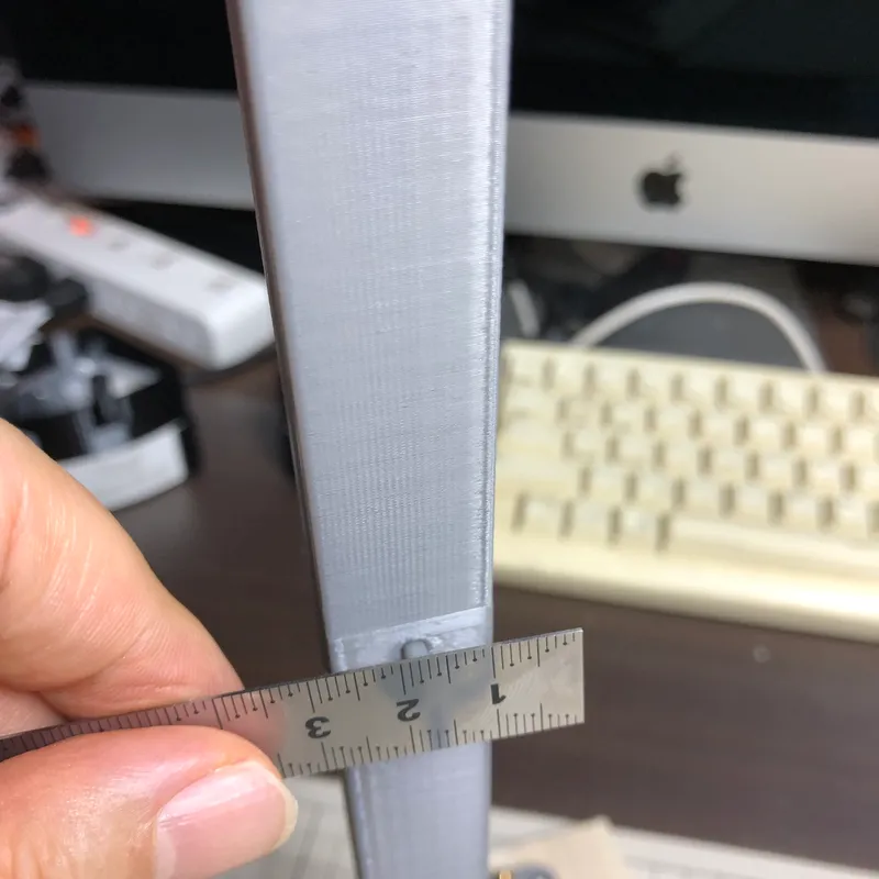
It is better to determine the dimensions of the “arm” so that the tip of the soldering iron does not hit the base plate. To do this, first attach an iron holder to the soldering iron and measure the distance from the tip of the soldering iron to the iron holder. In the case of my soldering iron, it was 86mm.
ハンダゴテの先端が土台の板にぶつからないようにarmの寸法を決めた方が良いでしょう。そのためにまずハンダゴテにiron holderを取り付け、ハンダゴテの先端からiron holderまでの距離を測ります。私のハンダゴテの場合は86mmでした。
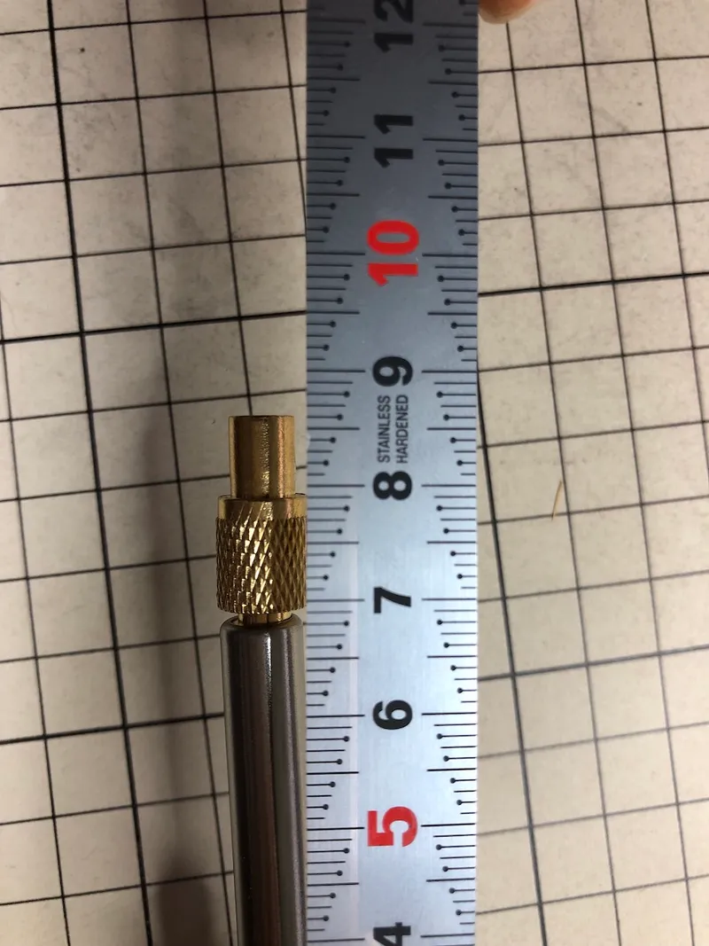
The parameters are then determined to satisfy the following relationship
そして以下の関係を満たすようにパラメータを決定します。
- base_thickness + pillar_slit_size/2 + arm_height - iron_holder_height ≥ measured distance
Assembly 組み立て
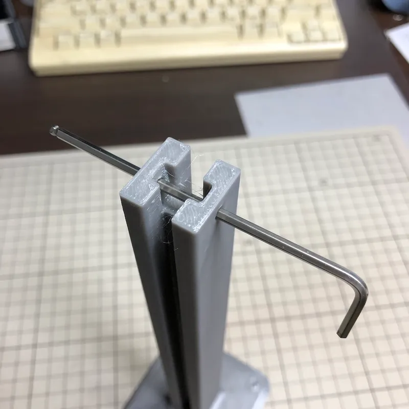
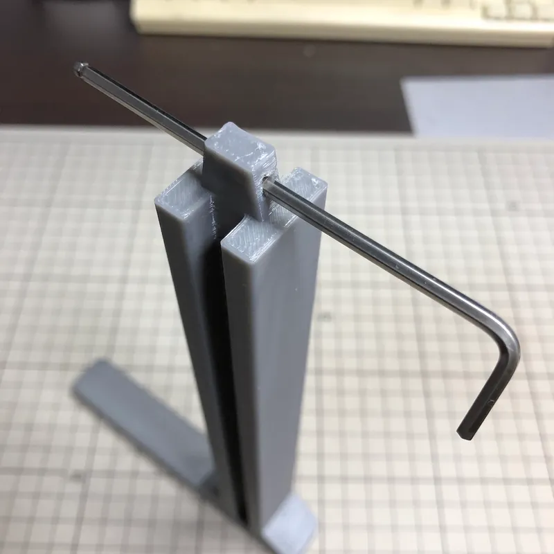
Step 1: Check the holes
Check that the 3 mm diameter holes in the lower and upper pillars are not blocked. In the photo, a 2.5 Allen wrench is inserted to check.
lower pillarとupper pillarの直径3mmの穴が塞がっていないか確認します。写真では2.5の六角レンチを差し込んで確認しています。
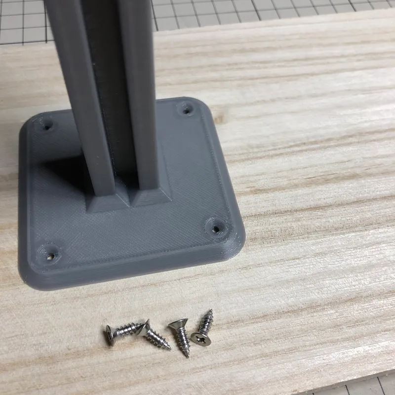
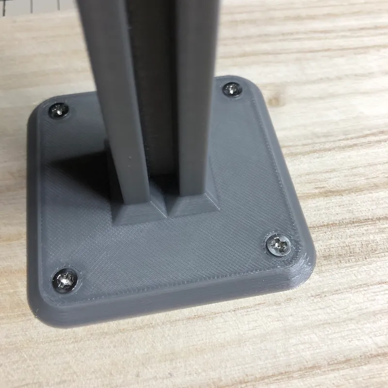
Step 2: Fix the “lower pillar”
The four screw holes for fixing the base to the base plate assume M3 tapping screws. If you use different screws, change the values of screw_hole_diameter and screw_head_diameter.
lower pillarを土台の板に固定するための四つのネジ穴はM3のタッピングネジを想定しています。違うネジを使う場合はscrew_hole_diameterとscrew_head_diameterの値を変えてください。
Step 3: Insert the “arm” and the “counter weight” into the “lower pillar”
Insert the arm and counter weight into the lower pillar in the orientation shown in the photo. Then check that the arm and counter weight move smoothly up and down without any snagging. If the print is clean but the movement is not smooth, increase the “gap” value.
写真のような向きでarmとcounter weightをlower pillarに差し込んでください。そしてarmとcounter weightが引っ掛かりなく上下に滑らかに動くことを確認してください。きれいに印刷できているのに動きが滑らかでない場合はgapの値を増やしてください。

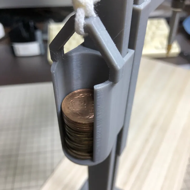
The counter weight is intended to hold a coin as a weight. Set the parameter coin_diameter to a value slightly larger than the diameter of the coin to be used. I set the value assuming a 10 yen coin.
counter weightには錘として硬貨を入れることを想定しています。パラメータcoin_diameterに使う硬貨の直径よりも少し大きな値を設定してください。私は十円硬貨を想定した値を設定しました。
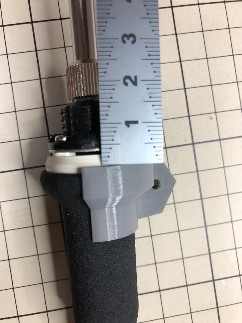
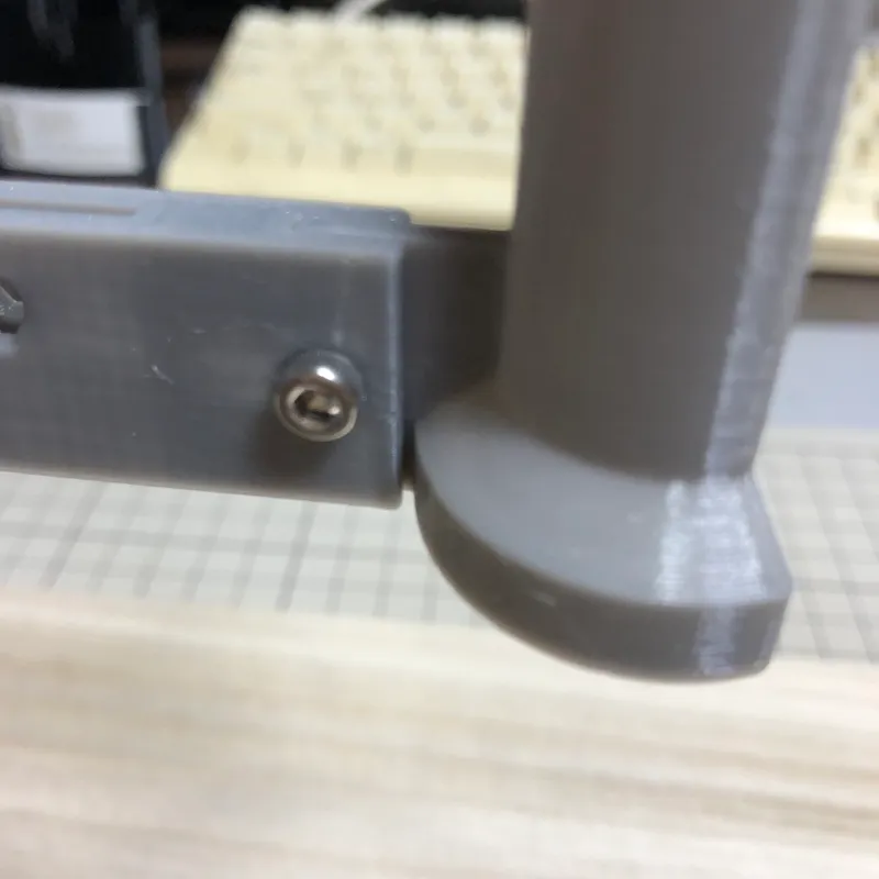
Step 4: Connect the “iron holder” to the “arm”
Fix the arm and iron holder with M3x8mm bolt and M3 nut.
armとiron holderをM3x8mmのボルトとM3ナットで固定します。
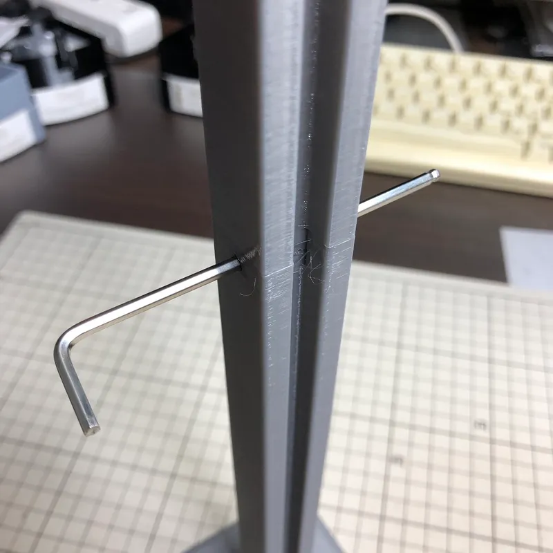
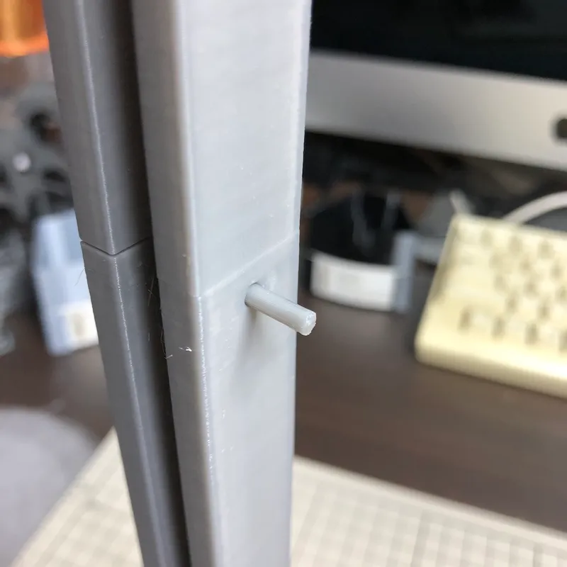
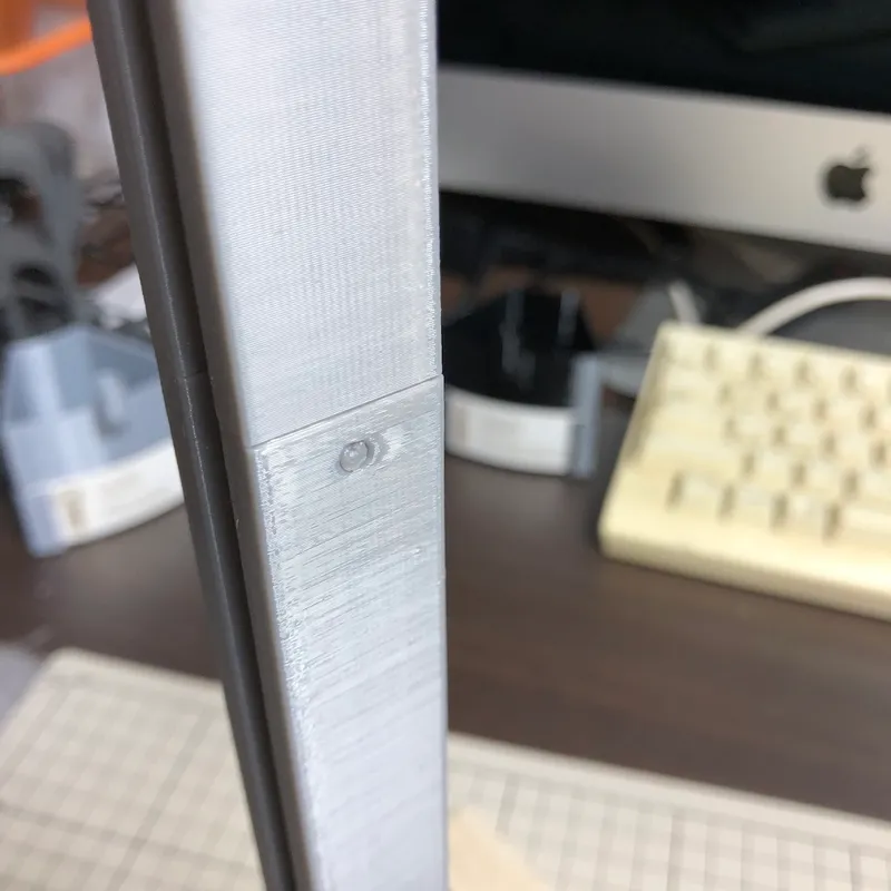
Step 5: Connect the “lower pillar” and the “upper pillar”
Connect the upper and lower pillars by inserting the connector pin into the hole identified with an Allen wrench. It takes a lot of force to insert it. It will hurt your fingers, so it is best to use something hard and flat as shown in the picture. Make sure that the connector pins do not protrude on either side. If they protrude, either the arm or the counter weight will be hit.
六角レンチで確認した穴にコネクタピンを差し込んで上下の柱を連結します。差し込むにはかなりの力を必要とします。指が痛くなるので、写真のように固くて平らなものを使うのが良いでしょう。コネクタピンが両側ともはみ出していないことを確認してください。はみ出しているとarmとcounter weightのどちらかが当たってしまいます。
穴は円形に、コネクタピンは八角形にしています。これは以下のサイトを参考にしました。
- https://makezine.com/article/digital-fabrication/3d-printing-workshop/tips-3d-printing-press-fit-parts/
- https://makezine.jp/blog/2015/09/tips-3d-printing-press-fit-parts.html (日本語)

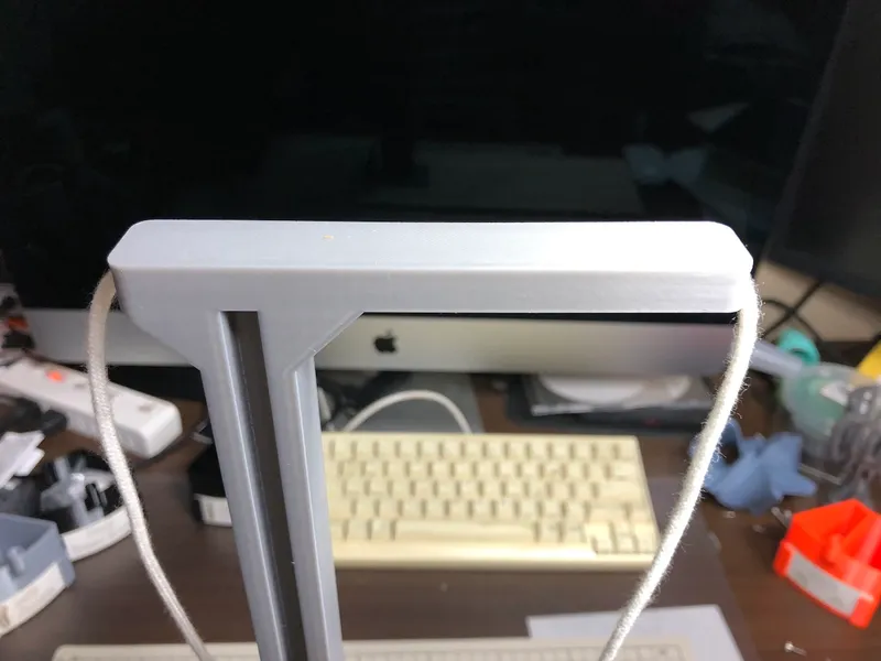
Step 6: Connect the “arm” and the “counter weight” with string
Pass the string through the hole in the upper pillar. Adjust the length of the string so that the arm can move from top to bottom.
upper pillarの上に空いている穴に紐を通します。そして両端をそれぞれarmとcounter weightに結びつけます。armが上から下まで動けるように紐の長さを調整してください。
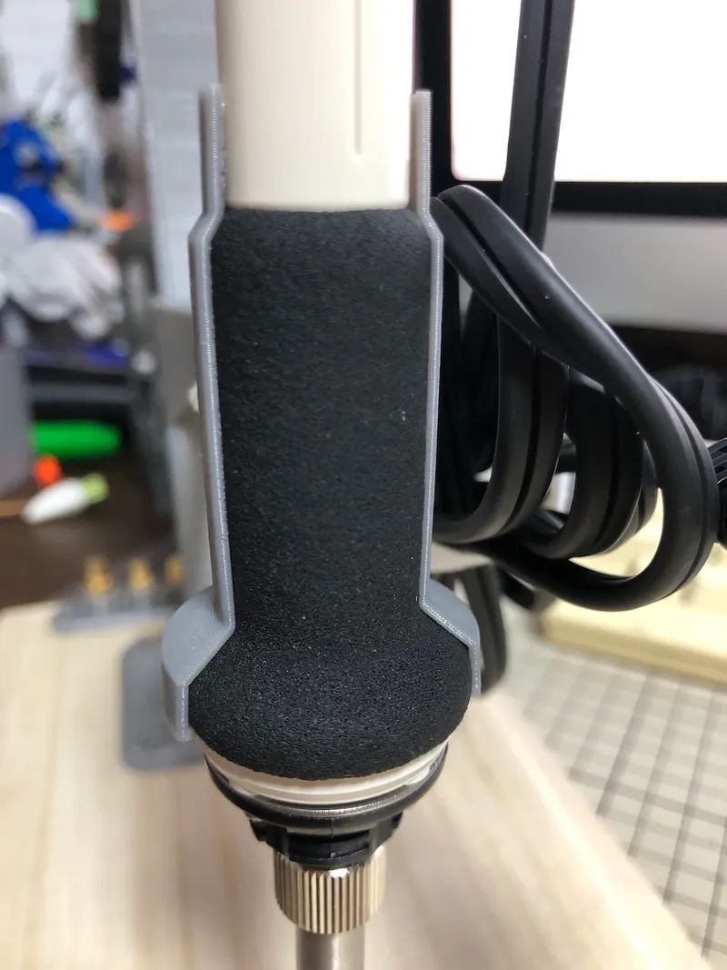
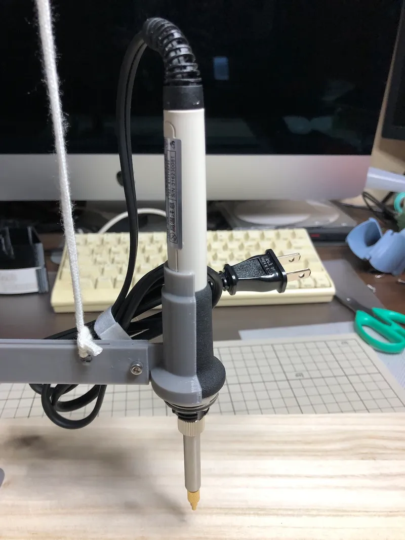
Step 7: Attach soldering iron and adjust weights
Finally, attach a soldering iron and adjust the weight as shown in the photo to complete the process.
最後に写真のようにハンダゴテを取り付けて錘を調整すれば完成です。
Parameters
Additional information おまけ
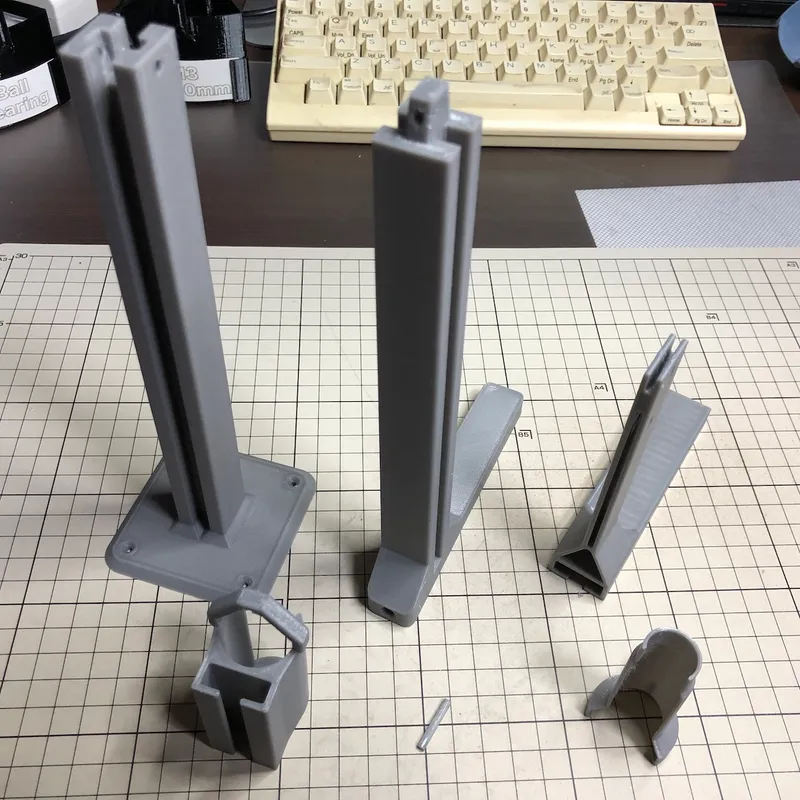
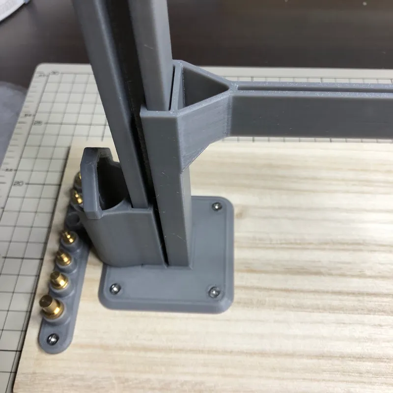
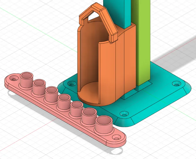
Shown next to the lower pillar is a "tip adaptor holder". It is for the following products.
lower pillarの隣に写っているのは「tip adaptor holder」です。以下の製品用です。
Tags
Model origin
The author marked this model as their own original creation.