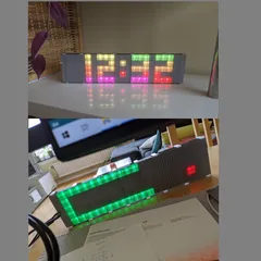
Modular LED Panel/matrix
Description
PDFModular LED panel
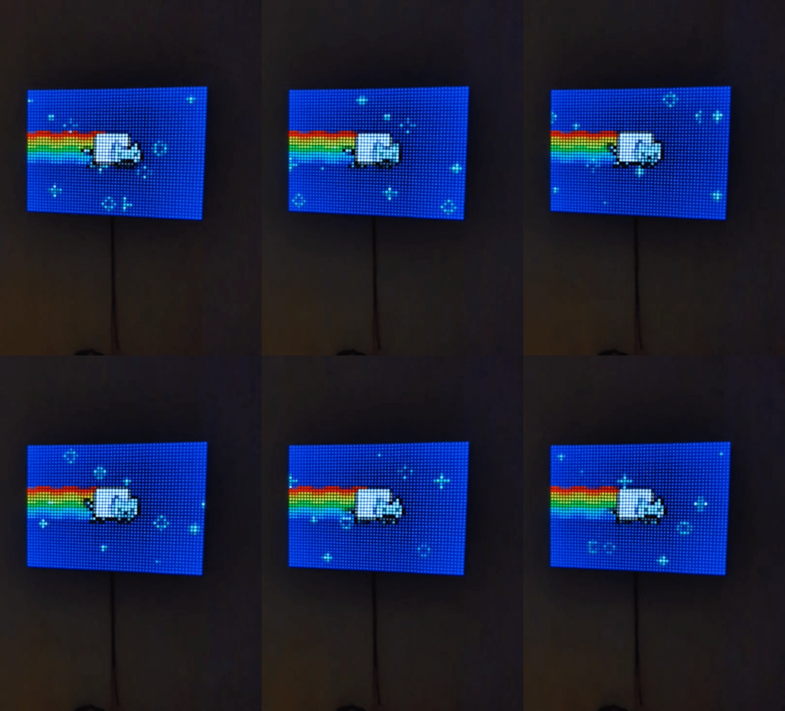
This modular LED panel consists of 8x8 LED tiles that can be connected in any (reasonable) matrix. You can just use one tile, 2x2, or connected 35 of them to make a 7x5 tile panel (2240 LEDs in total) as I did.
Each panel is 132x132 mm, and uses a LED spacing of 16,667 (100/6) mm, which is equal to LED strips with 60 LEDs per meter. I used sk6812 RGBW LEDs to get a slightly whiter white color, but any ws2812 or similar also works. They just need to have the correct LED spacing and three connectors in each end, 5V, GND and data.
Each tile has a back plate, a grid, side walls and a "glass" panel (more about the “glass” below).
Parts needed (quantity depends on your panel size)
- LED strip with 60 LEDs per meter. I used the 5V RGB NW (Natural White) 5M 60 IP30 from Aliexpress. IP30 is important here to get a thin strip. Any other rating (IP65, IP67) will be too thick. Each tile consist of 64 LEDs.
- 1mm copper wire for connecting power supply. ~200mm per tile, plus 60mm per each vertically connected tile.
- 0.6mm copper wire for connecting data lines. ~116mm per tile. You can also use isolated copper wire (coil wire) if you up for removing the isolation for all connection points.
- 6cm 22 AWG wire for 5V, GND and data. 8x red, 8x black, 2x green per tile. For smaller panels, ethernet cable cables work well. I did by pre-cut and pre tinned wired due to not wanting to cut and pre-tin 630 wires for my 7x5 panel.
- M3x14mm screws for connecting tiles into a panel. ~4-8 per panel.
- M3 nuts. ~4-8 per panel.
- M3 short threaded inserts for fastening hooks and similar.
- A power supply. This depends on how many tiles you want and the type of LEDs you choose, as well as the max brightness you want to be able to use. I found this guide to be helpful. In my case, I went with roughly 1.5A per tile (per 64 LEDs). Important it to buy a quality power supply from a well known source (like Mean Well), otherwise you might end up with something that will burn your house down or will make you go crazy due to coil whine.
- Suitable AWG 16/14/12 wiring for routing the power rails to the power supply.
- A microcontroller. Can be anything really, you just need a couple of pins for data. The number of pins depends on size of the panel and the desired refresh rate. More on that later.
- Soldering iron.
- 3D-printer.
- Endurance for doing the same task over and over.
Technical overview
Each panel has eight strips. The data for each strip is connected in a snake pattern. E.g. data comes in on top left, then connects to the second row on the right side. The second row connects to the third row on the left side, and so on.
The strip needs power, 5V and GND. The 5V is connected on the left side and GND on the right side. the GND connection on the left side and the 5V on the right side is not used.
All the 5V as well as the GND connections are joined on the back side.
Version history
- 2023-05-07 - Added 3MF file for printer settings for the glass. Added note about elephant foot compensation.
- 2023-05-07 - Initial publishing
Tile printing and assembly
This is how to assemble one tile.
Print instruction for a tile
Back plate, gird and walls are printed in the most black color available. This is to not bleed light between the grid, and to reduce color pollution by reflection. I printed all parts in Prusament Jet Black.
All prints are with a 0.6mm nozzle. The thickness (0.65mm) of the outer wall is chosen for this nozzle size to get the proper combined wall thickness when putting two panels together, to match with the grid width (the wall thickness is half the size of the grid wall width).
Suggestion is to print a cut of the grid and a cut of the normal (0.15mm) back plate to and do a test fit first. If the fit is too tight/loose, try one of the other back plates.
Print:
- One back plate: 0.2 layer height, 10% infill, 2 perimeters. Face the text upwards.
- One grid: 0.2 layer height, 15 % infill, 2 perimeters. Face the X:es upwards.
- One wall: 0.2 layer height, vase mode.
- Six power supply holders. 0.2 layer height, 100% infill, 2 perimeters.
Assembly
While printing, cut the LED strip into smaller strips of 8 LEDs per strip. Trim the two edges with connections slightly so they with within the walls without protruding too much. Strips usually have a dotted white line where to cut. You want leave slightly less of the edge.
On the back of the back plate, there is an arrow and a label IN. With the arrow pointing upwards and the IN label in the top left corner (if viewing from underneath), place the strips in a snake pattern.
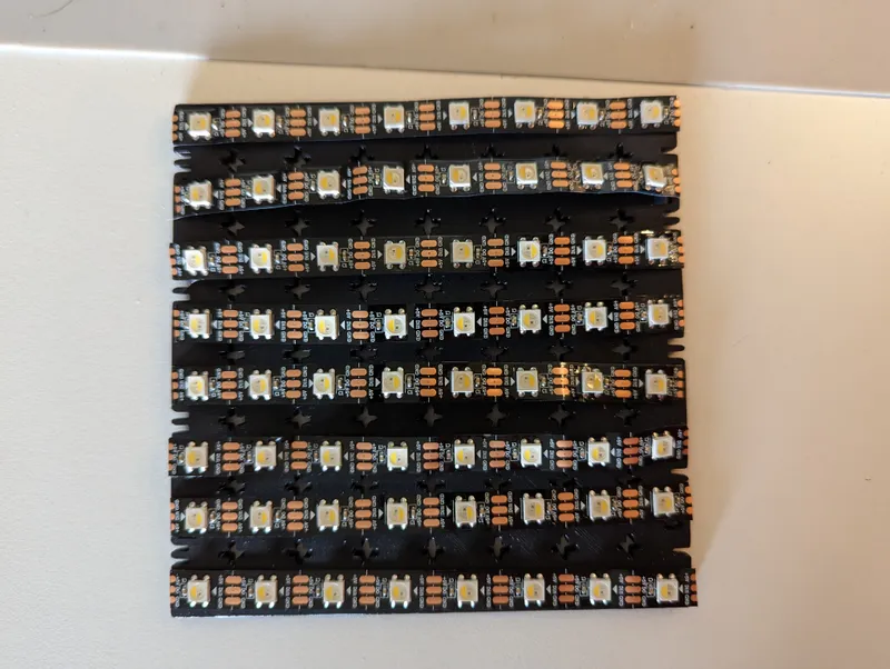
The arrows should go left to right on the first row, right to left on the second row and so on. The bottom row should go right to left.
Before pushing on the grid, notice that left and right side of the grid has notches on them.
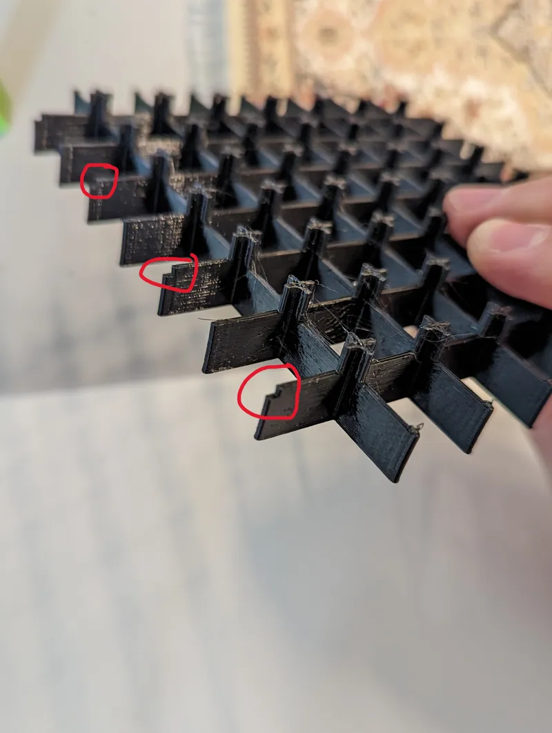
Rotate the grid so there is a notch between the first and the second row to the right.
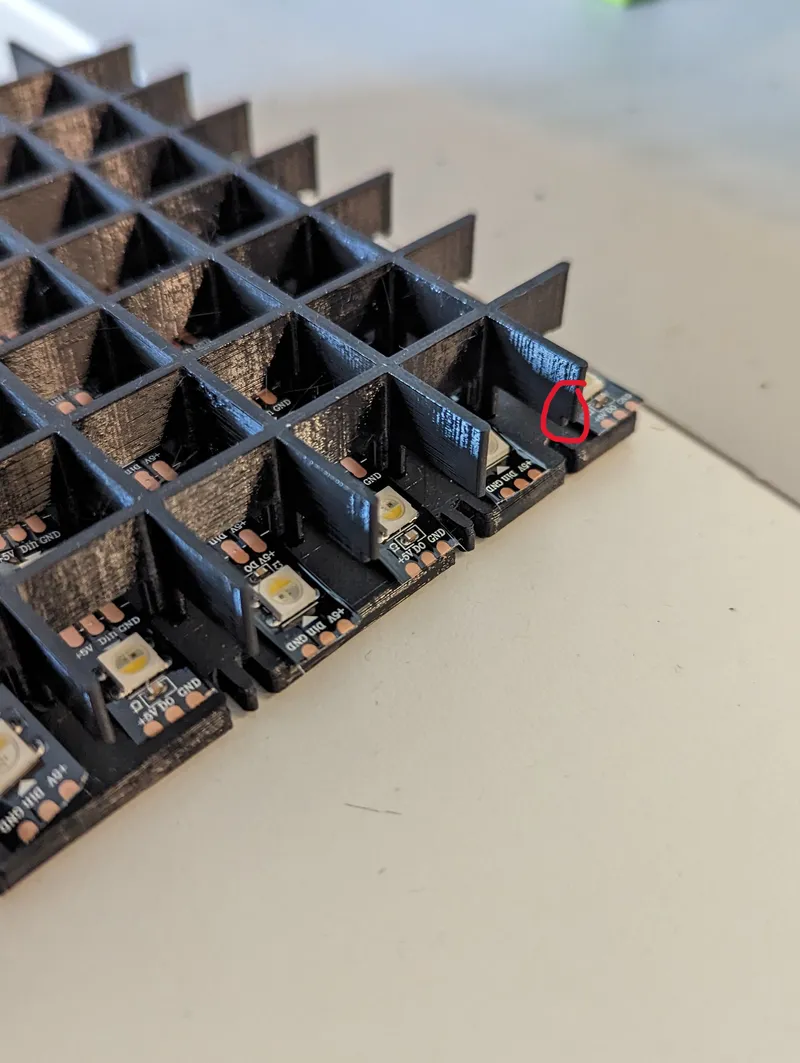
Align the strips and push the grid onto the plate. Make sure to push it all the way in and that the strips are aligned and not mushed. The grid has a quite fit. If you struggle to push it on, make sure all X:es in the bottom plate are clear from debris.
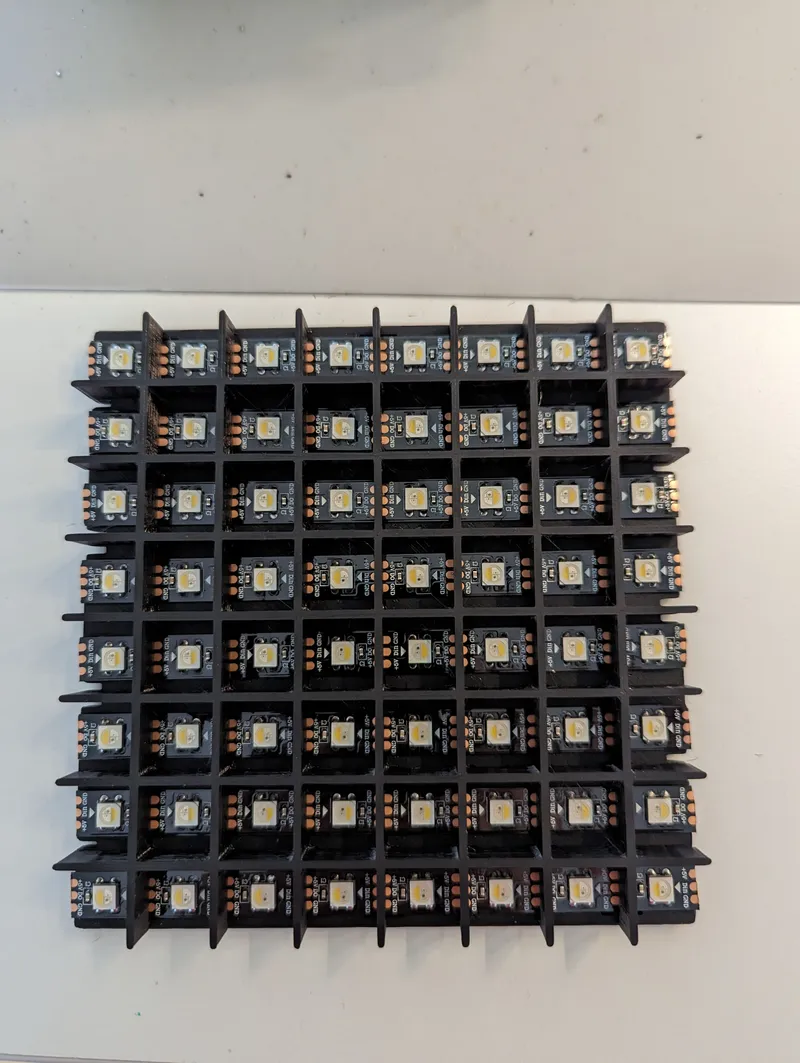
Using a sharpie or preferably UV curable solder mask, mask of the power supply not used. The backside of the back plate indicate the polarity. If it says 5V (left side) its the 5V side, so on this side you want to mask the GND. And on the GND (right) side, you want to mask off the 5V.
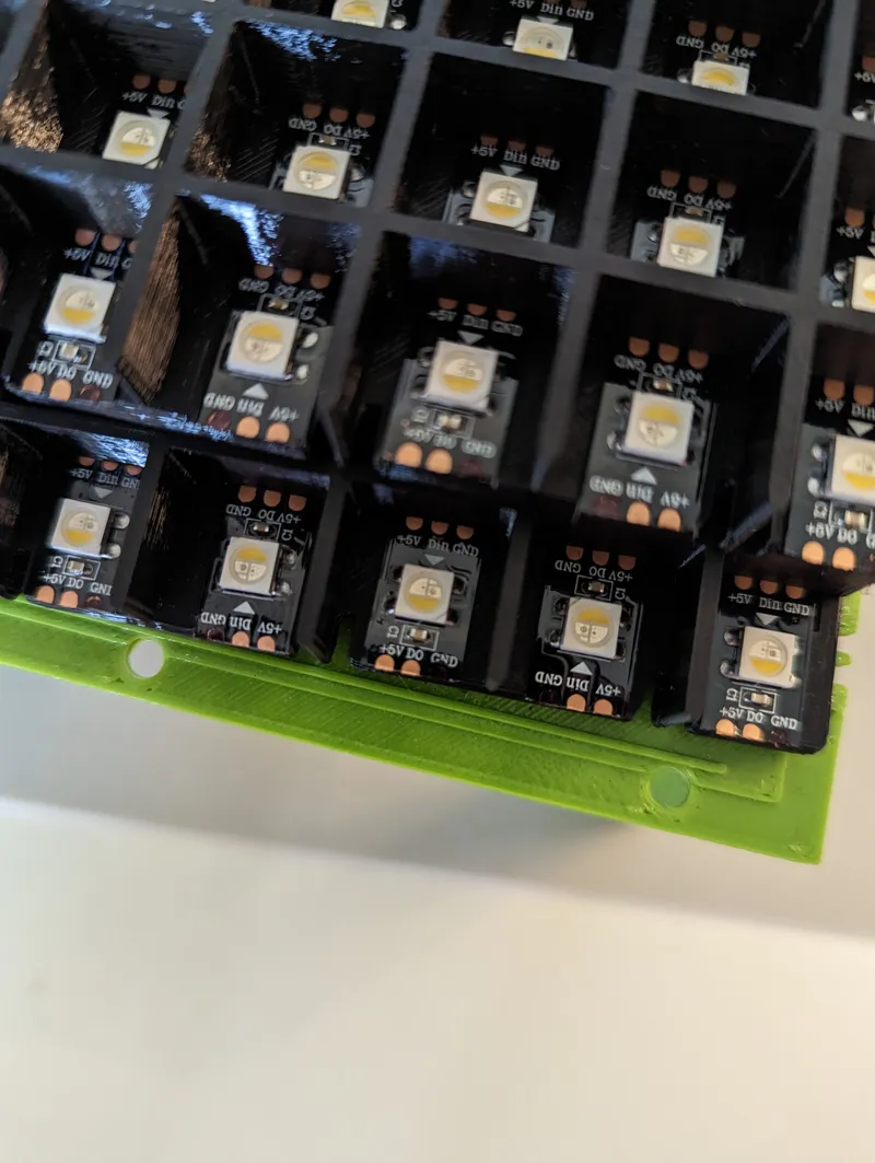
If using a sharpie, do this at least three times and wait for it to try in between. This is to ensure that the connection is isolated.
With the soldering iron, thin all non isolated pads.
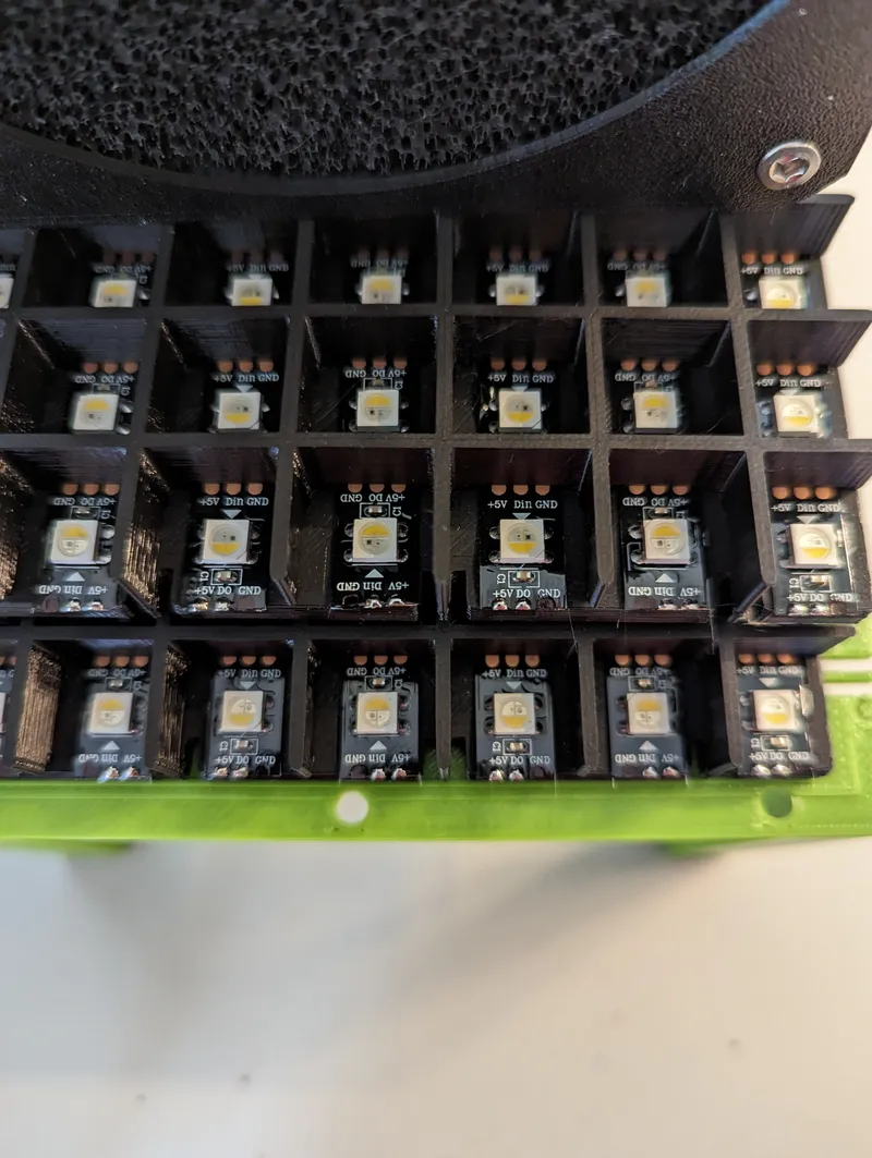
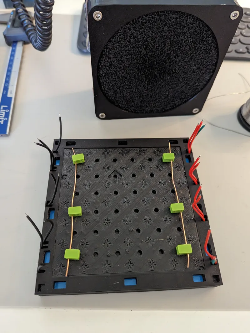
Bridge the data lines using the 0.6mm wire (or similar). This will be first row to second row on the right side, second row to the third row on the left side and so on. The wire should go through the notch in the grid. Repeat on both sides.
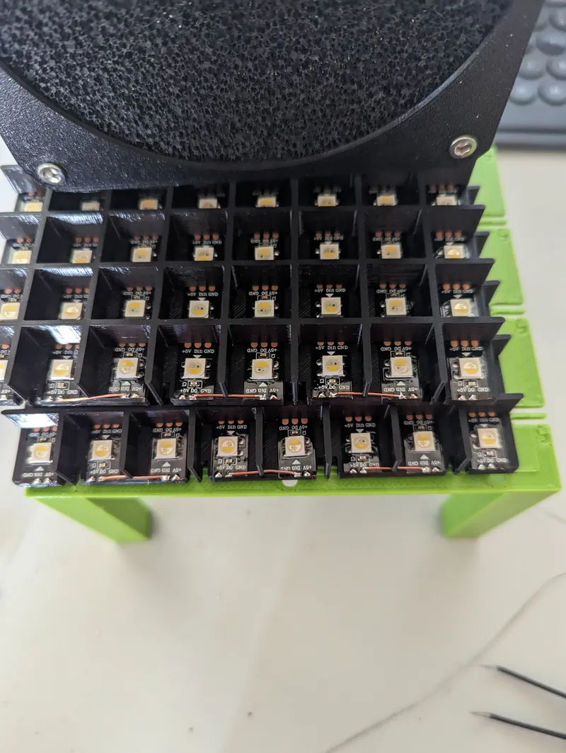
Solder the 6 cm cables on the 5V and the GND pads.
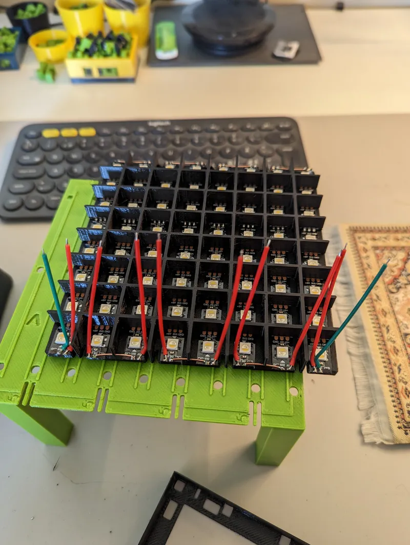
Solder them from the “inside”. E.g. so they later can be bent backwards without putting to much stress on the pads. Repeat on both sides. Also solder the data IN and OUT (green in this photo) on the left 5V side.
Fold the 5V and GND connection down in the closest cutout in the bottom plate. While doing so, make sure to hold/put pressure on the solder pad to not rip it of when bending the wire.
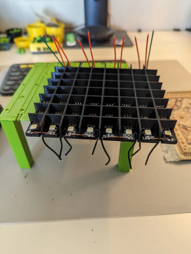
Once wires folded on both sides, route the wires through the bottom of the cutouts in the wall part.
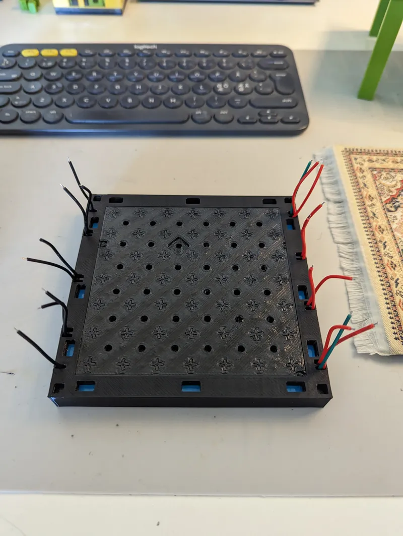
Using the 1mm copper wire and six power supply holders, form two rails.
Then solder the eight 5V and the GND to each rail.
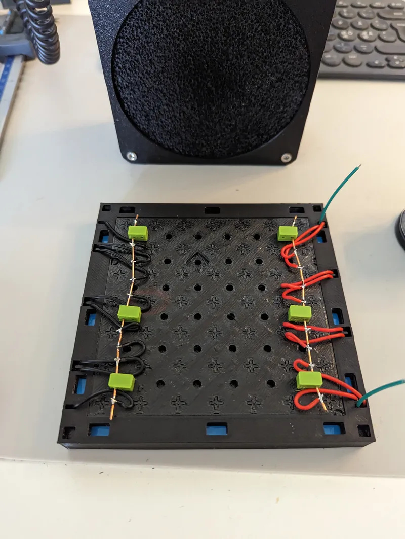
You have now completed the assembly of one tile. Repeat for how many tiles you want in your panel!
Joining multiple tiles
A tile is can be connected to any other tile using any of its four edge sides. On the backside, they will be hold together using clamps, and on the frontside the overlapping glass will do the trick. For smaller panels, you usually only need one clamp per edge. For larger tiles, you want to connect two or three ones if for rigidity.
To print for one clamp
- Two ½ clamps: 0.2 layer height, 100% infill, 2 perimeters. Print laying down in its side.
- Clamp middle plate. 0.2 layer height, 100% infill, 2 perimeters. The reason for this being a separate part is to be able to adjust this for a tighter or looser fit. If the clamp doesn't clamp enough, just scale this down in the X/Y plane.
Insert a M3 nut in one of the clamp. Sandwich the middle plate in between the plates and insert the M3x14mm screw and tighten slightly. While facing the arrow on the backside of the tile upwards, install the clamp between the tiles you want to join. Repeat for each tiles you want to join. Make sure to do this on a flat surface.
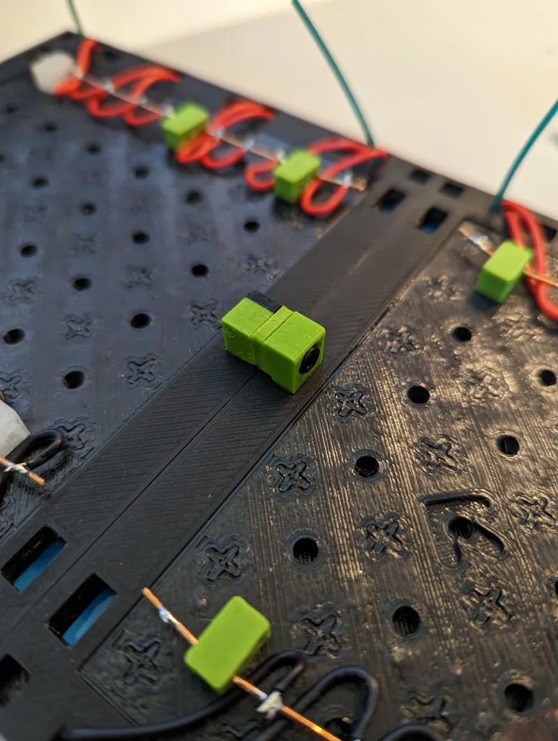
Then join each vertical power line using the 1mm wire. E.g. join the 5V from one tile with the 5V on the next tile, and same for GND. Depending on the power supply and the size of your panel, you can wire each of these rails on separate cabling to the power supply. For smaller tiles, you can join all rails into one rail using some thicker isolated wire.
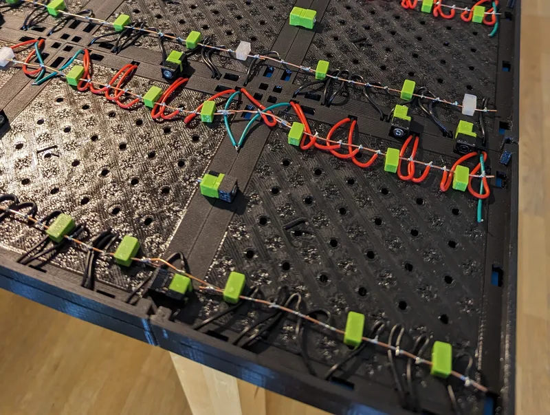
Also join each the OUT data line one one tile to the IN data line on the next tile. Depending on the size of your panel and hardware, you can either link all tiles together in a long single data line, or use a single data line per column. for larger panels where the total number of LEDs is larger than 512, then you might want to divide into separate data lines to increase performance/refresh rate. In my 7x5 case, each column is its own data line, e.g. there are seven data lines connected to the microcontroller.
Glass/Diffuser
To hold the tiles together on the frontside and do diffuse the LEDs, we use clear PETG (in my case, Prusament PETG clear). The glass is printed in sizes that will overlap several tiles, and thus holding them together. The fit is important. Too lose and they will fall off, to tight and you will not get them on. I have provided different tolerances. Print a test part and see how it fits. One thing to note that any intolerance will add up with larger glass sheets. E.g. if one square of the glass fits well, its not necessarily so that eight square will fit well.
The glass comes in different sizes, and with the provided sizes you can build any panel size. You want the glass to always overlap one or two panels (except for the last glass).
E.g. if you have a 2x2 panel, you want to print:
- One 10x10 glass
- Two 6x10 glass
- One 6x6 glass
This will make a overlapping pattern and cover the panel. For larger panels than 2x2, you want to fill out with 8x8, 8x10 and 8x6. For my 7x5 panel, I printed one 10x10, eight 8x10, fifteen 8x8, two 10x6, eight 8x6 and finally one 6x6.
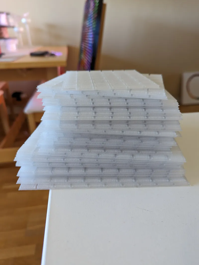
Print settings are slightly custom here to make the glass diffuse “enough”. This is also a personal preference, so you can change this until you get a glass that you like.
- glass: 0.2 layer height, 50% infill using rectilinear pattern, monotonic top and bottom infill pattern, fill angle 90°, infill/perimeter overlap 25%, 1 perimeter. Make sure elephant foot compensation is enabled, and that the first layer is not too squished. If to squished/not compensated for (and thus slightly oversized), adjacent glass will not fit with each other.
The 3MF file with all the settings can be found in the glass/normal fit folder.
Skirt
Finally you want to print a skirt. This will sit on the edges of the back to hide the internals.
Print:
- One skirt corner for every corner you have. 0.2 layer height, 15% infill, 2 perimeters.
- One skirt edge for every edge you have. 0.2 layer height, 15% infill, 2 perimeters.
Hooks
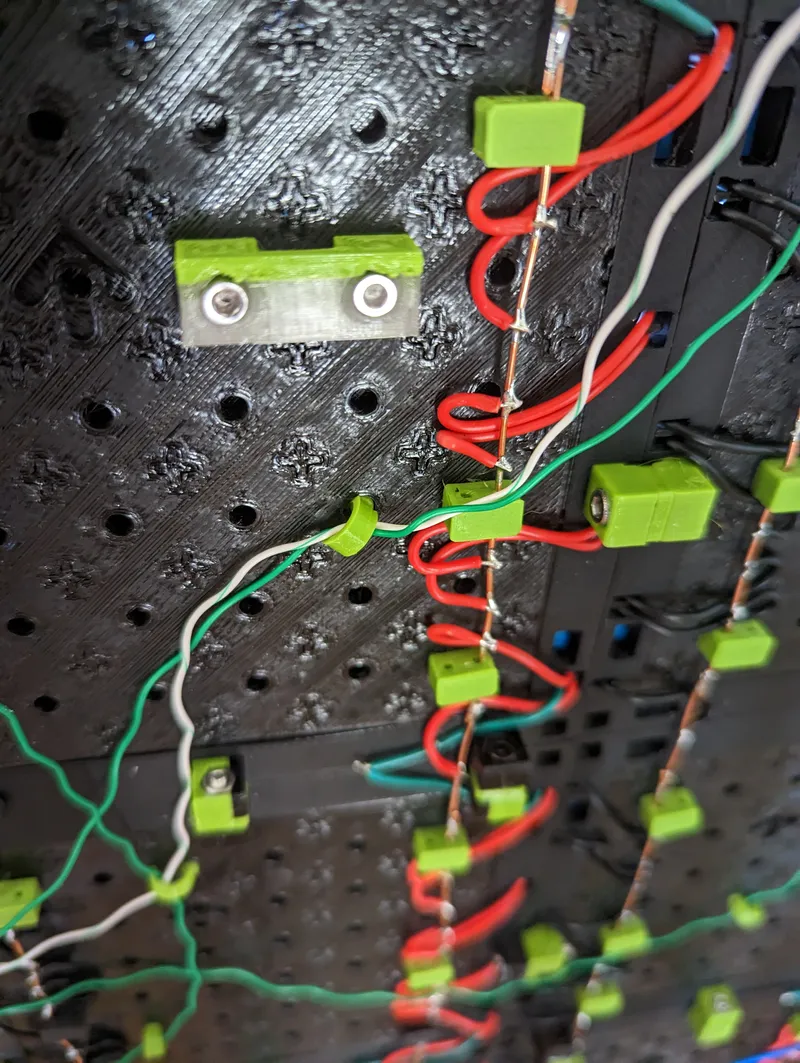
These are for hanging the panel on the wall or for other attachments. All the holes on the backside of the back plate are size for short M3 threaded inserts. Here you are free to mount/attach various stuff like microcontroller, hooks etc. I used the following hooks for hanging the panel on the wall:
- hook: 0.2 layer height, 15% infill, 4 perimeters. Print laying on the side.
Electronics
You need at microcontroller with at least one data pin, and enough RAM to hold one image with 24 bits per LED/pixel. In my project, I'm using a ESP32-S2 (Wemos S2 mini) with 2MB external RAM.
I have uploaded a simple program that uses Platform I/O and the Arduino framework together with FastLED. It supports uploading images and GIFs using two scripts. You can use this as a base for your own software, or just roll your own code. Code is the most fun about this project after all.
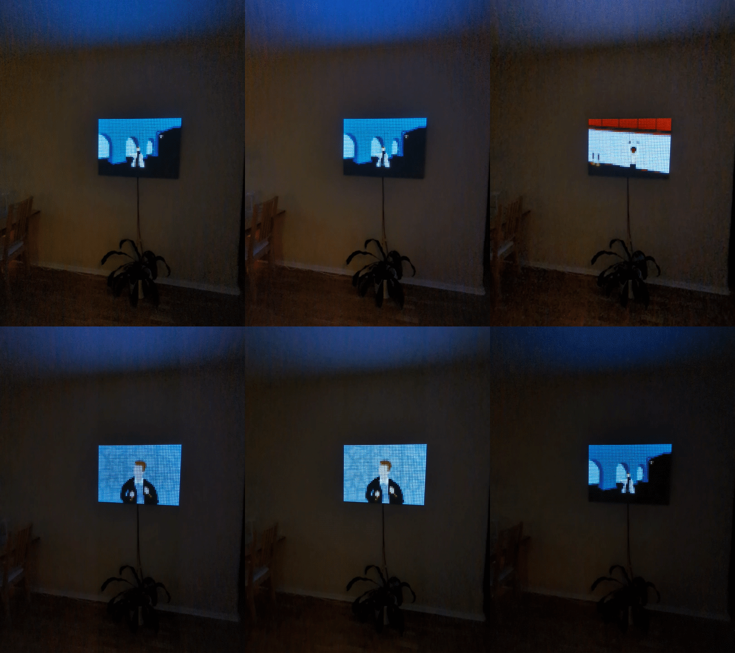
Enjoy this GIF of a movie of a GIF on a 7x5 tile panel.
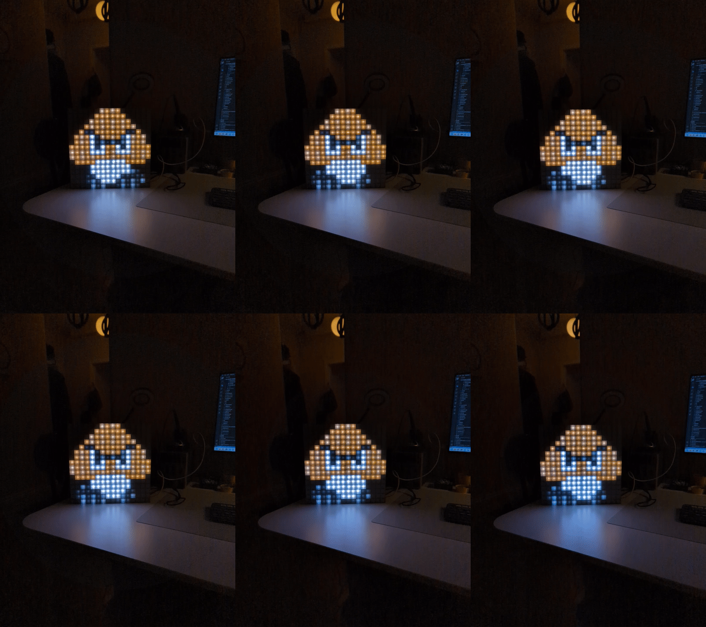
2x2 panel.
Extras
Backside view of the 7x5 tile panel, with a Wemos S2 mini in the center. Data for each column is connected on a separate pin. The power for the two left columns are joined, same for the two right columns and for the three center ones. This is to have separate cabling for these three sections. Ground is joined on power supply side.
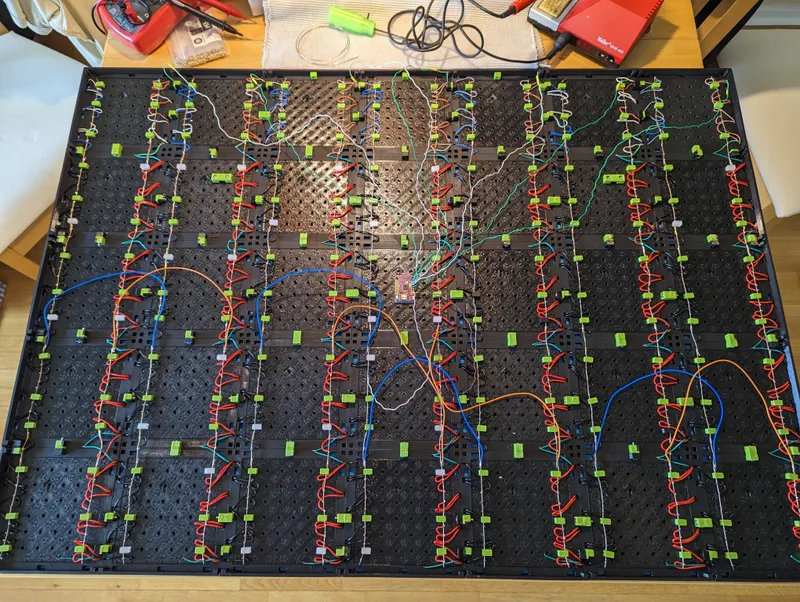
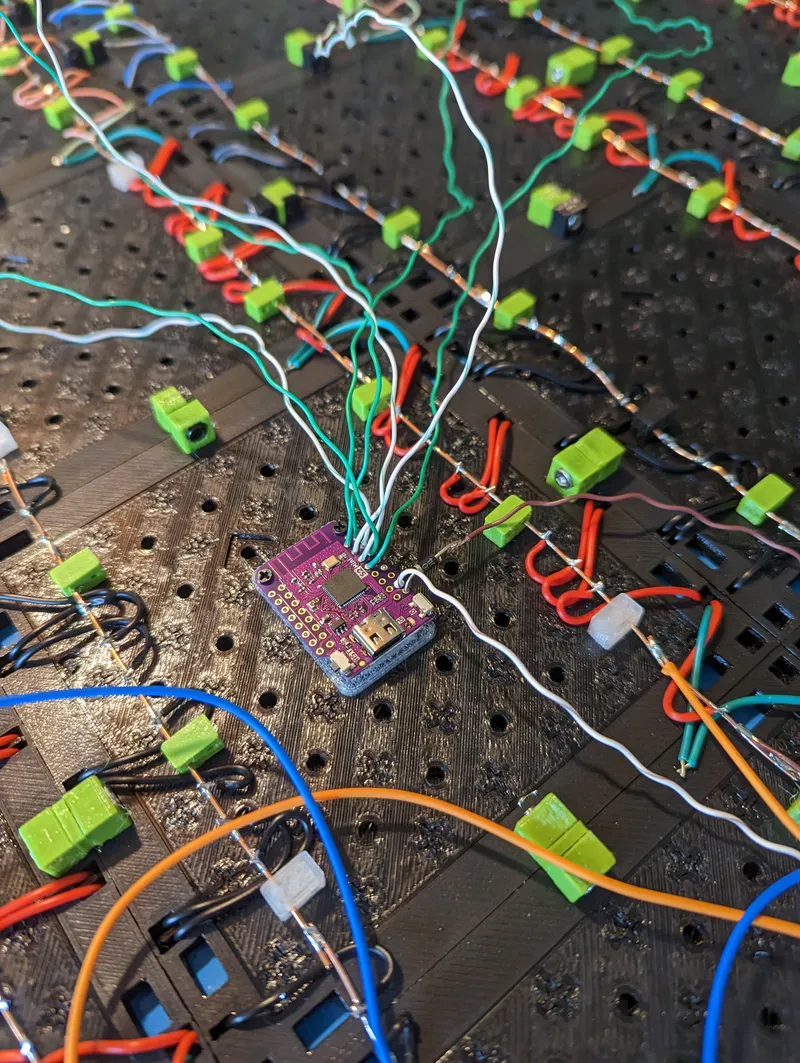
Note the diode connected to the 5V of the ESP32. This is to only draw power from the LED supply, and not to try to drive them. This can happen if you don't have supply connected but only connected via USB. Poorly designed USB hubs will not enjoy trying to power all the LEDs (from my own experience…).
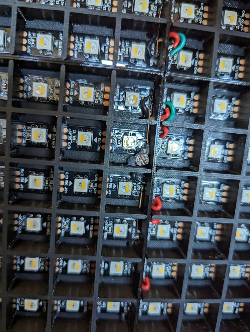
Also added is a LDR light sensor to one of the center squares, using the existing wire cutout. This is to measure the external brightness and adjust the light of the LEDs accordingly. When measuring the brightness, the LED for the square where the LED is has to turned off quickly.
Tags
Model origin
The author marked this model as their own original creation.

