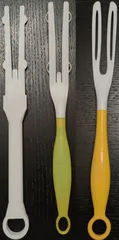
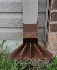
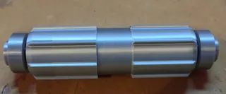
Bambu AMS Feeder Rebuild Kit
Description
PDFReplacement gear sets and first stage feeder funnel for the Bambu first stage feeder assembly.
This includes gears:
- Worm Gear (on the motor shaft)
- Helical Gear (meshes with the worm gear)
- Small Cluster Gear (small gear on the long horizontal shaft, next to the helical gear)
- Large Cluster Gear (meshes with the small cluster gear, drives both the extruder gear and spool roller gear)
- Extruder Gear
And this includes a first stage funnel, split into 3 parts to make the print easier. My hope is that we as a community can customize the feeder funnels by plugging on a different funnel onto the main body and arrive at a more reliable design than Bambu.
- bambu_funnel_top: The funnel part that is begging for a redesign. This is a recreation of the stock design (for now)
- bambu_funnel_middle: The most complicated part and houses the filament runout sensor and roller bearing
- bambu_funnel_buttom: This reuses the clip and PTFE connector
Printing the Gears
It's best to print each gear one at a time to avoid retractions. You will probably have a better quality print with a 0.2mm nozzle, but you can't print abrasive filaments with that.
Helical Gear
Since this gear seems to have a lot of sheer stresses, print this with nylon carbon fiber, like PA-CF or PAHT-CF from Bambu. And since it's pretty tiny, I printed with the finest layer height, 0.08mm with 100% infill. Also include supports and print with the smallest hub facing down on the build plate. The two sides are different on this gear. If you have the front of the feeder facing you, the left side of the gear has a 2.5mm hub. You can also see 3 bumps on the yellow gear, indicating the left side. The right side has a 2.0mm hub, so you have to look very closely to spot the difference.
Worm Gear
The worm gear is a difficult print because it's so tiny and tall. It might be better to print it with 0.2mm nozzle and a non-abrasive filament like ASA. I printed mine with a 0.4mm nozzle and a 0.08mm layer height. The bore was off-center and the threads needed a lot of cleanup work. The gear mesh in operation is also quite noisy.
After printing the gear, disassemble the AMS and pull the bad feeder out. Then follow Bambu's guide to disassemble the top cover.
To remove the shaft with the cluster of gears:
- Take lots of pictures as you do this!
- Use a small flathead screwdriver to push the brass bushings out, just enough to pinch the other side with the flange with some vise grips and pull them out
- After the bushings are out, spread the plastic shaft mounts and pull the whole shaft with the 5 gears attached to it
- Find a small socket that fits around the shaft, but contacts the yellow gears
- Find a small screwdriver that is smaller than 3mm diameter
- Use the screwdriver, socket, and hammer to tap the gears off the shaft
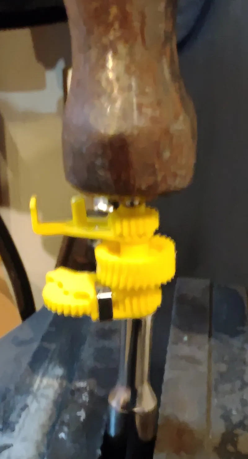
Working backwards, install the new gear:
- Pick a side, tap on a gear set. (Either the left side that drives the spool, or the right side that drives the extruder) Use a socket to pound it on a little past the end of the shaft
- Tap on the new helical gear
- Tap on the other side's gear set.
- Place them back in the plastic shaft holder
- Add a little light machine lube to the brass bushings and tap them on
- CHECK THE TIGHTNESS. After I put the brass bushings on, the movement was very tight. I took them back off and used an 1/8" drill bit to open up the bushing bore a little bit more. It was so tight that the motor wouldn't even move, and I suspect that might have been the original problem that stripped the gear out.
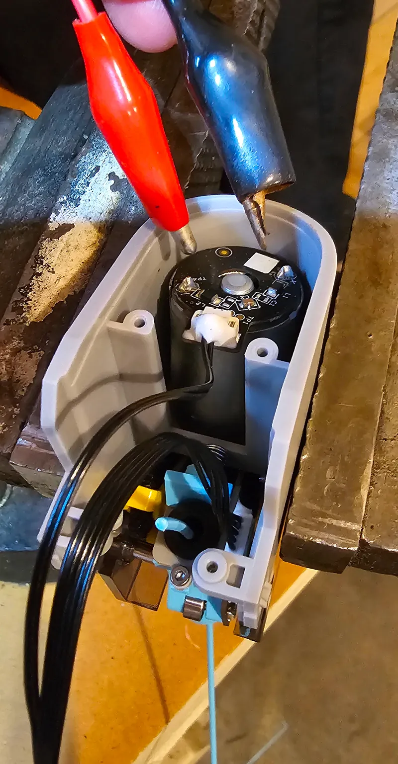
- If you have a nice 3 - 6V DC power source, you can spin the motor up manually by applying some juice directly to the positive / negative terminals. That way you can test that the gears mesh and the tolerances aren't too tight.
It should look like what I have in the second photo. Reassemble everything else and test!
Print Settings
Printer:
Bambu X1C
Rafts:
No
Supports:
Yes
Resolution:
0.08mm
Infill:
100%
Filament:
How I Designed This
I wanted to get up and running quickly, so I disassembled the feeder and measured the helical gear:
- Outside Diameter: 16.20mm
- 30 teeth
- Left side hub height: 2.5mm
- Right side hub height: 2.0mm
- Bore diameter: 3.0mm
- Helical angle: 10 degrees
- Gear width: 6.0mm
- Total width including hubs: 10mm
- (guess) Reference diameter: 15.20mm
- (calc) Module: 0.5066mm
Using these numbers, I just plugged the necessary stuff into FreeCAD gears workbench, added some hubs, then drilled a pocket for the bore.
The First Stage Feeder Funnel
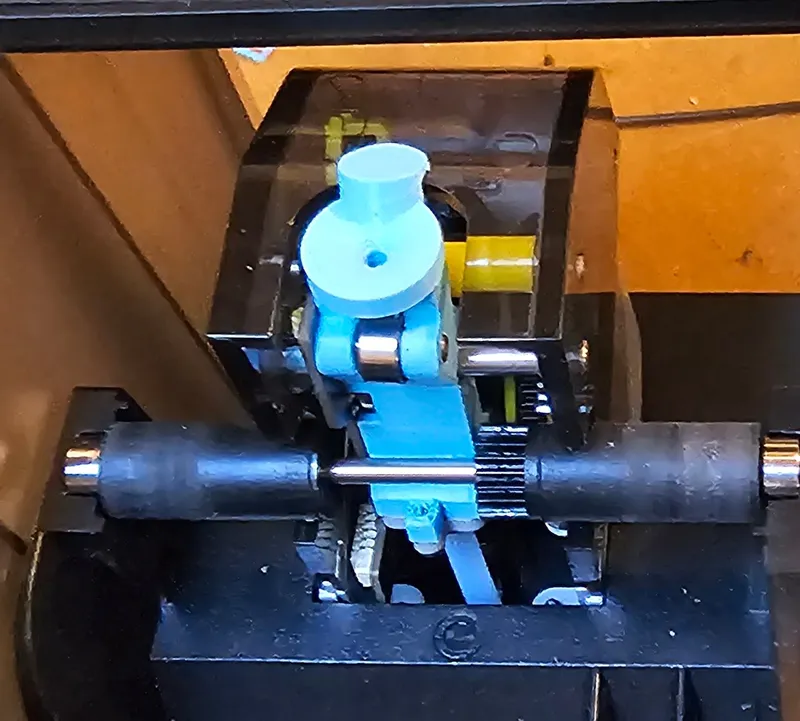
Printing
The feeder funnel is a complex object and a little bit difficult to print. The top and bottom is easier. Just print them with the largest flat surface on the build plate.
For the middle section, orient with the side facing down, and choose the side with the shortest cylinder. If you're facing the “front” side of the feeder if it were installed in the AMS, this is the left side. See the bambu_feeder_rebuild_kit.3mf for a better description.
Print the middle and bottom in PLA with a 0.2mm nozzle. You can attempt a 0.4mm nozzle, but I don't think it's going to work. For the top funnel, you can get away with a 0.4mm nozzle and an abrasive filament.
Assembly
Take the 3 pieces of the body and glue them together with epoxy, then clamp tight to dry.
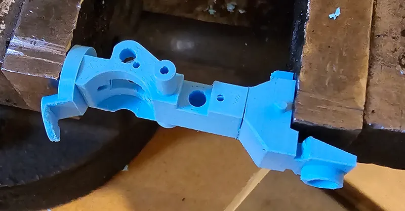
Use a small Dremel bit to clean out all of the small pockets. Use a drill bit to ream out the filament tunnel. If you have a 2mm bit that would be perfect. If you only have Imperial bits, start smaller and test fit a piece of filament through the funnel and feel for anything that catches.
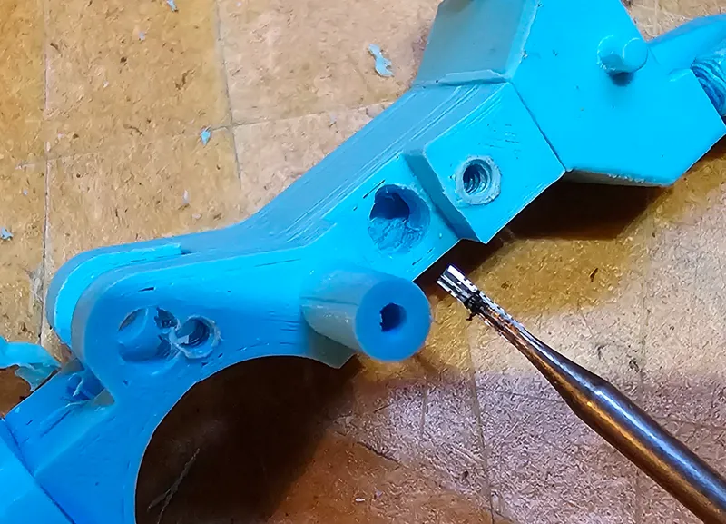
Plop the filament sensor thing into the slot, flat side up.
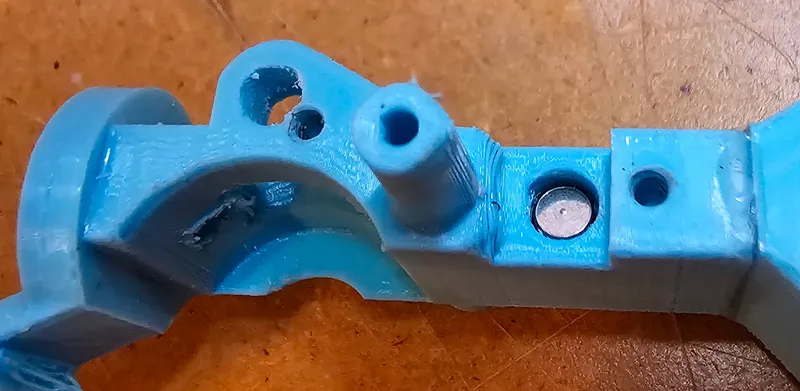
Screw the PCB onto the funnel feeder and test. Use a digital multimeter to probe pads TP7 and TP8 on the bottom of the board. These are connected to the filament runout switch. Slide a piece of filament in and out and confirm that the circuit closes with filament IN, and opens when filament is OUT. (This might require an extra set of hands)
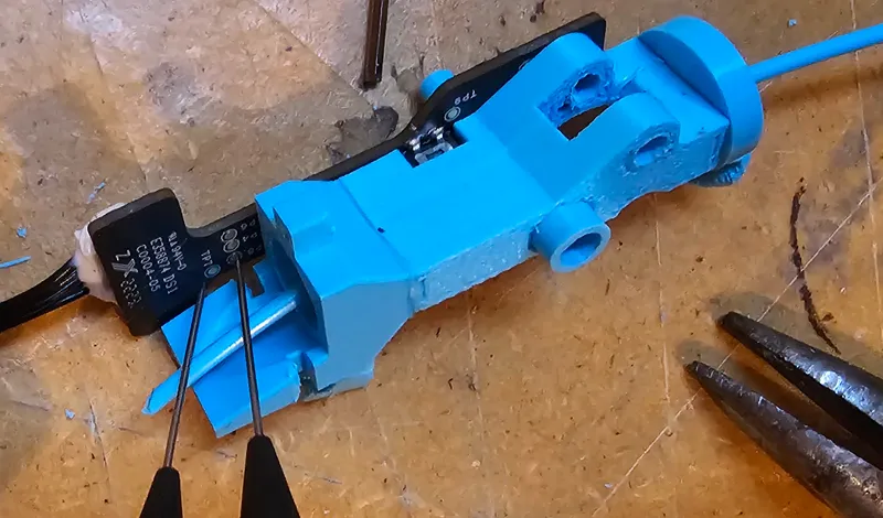
Install the PTFE fitting and the clip from the original feeder.
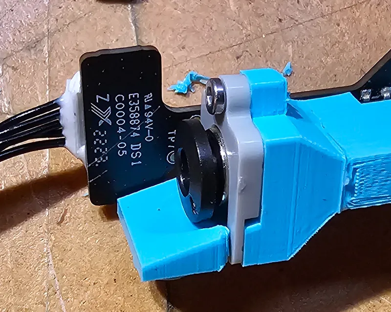
Install the roller bearing and install the feeder funnel into the housing.
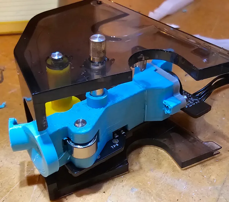
Reassemble the rest of the first stage feeder, and bench test it with 6VDC. If you stick a piece of filament in the funnel and apply voltage in the correct direction, the motor should feed the filament through and spit it out the PTFE fitting. This test is a must if you printed gears too. It saves yourself a lot of time disassembling the AMS.
If everything seemed to go well, reinstall the feeder into the AMS and try out some prints!

Category: 3D Printer Parts
Tags
Model origin
The author marked this model as their own original creation. Imported from Thingiverse.

