Ender 5 Triple Z (E5TZ)

Budget and simple triple Z implementation for Ender 5/Pro
48
139
0
2402
updated June 27, 2023
Description
PDFV2 is now available at this printables page.
If you want to print fast, I recommend looking at V2
NEW: step file for V1 (May 2023 version) added
MAY 2023 UPDATE TO V1
- Reinforced arms
- M3x4mm heatset insert supported - if you use heatset inserts use the round holes on the face that the screws enter, otherwise put the usual hex nuts on the nut traps on the other side
- full set is now indeed a full set(thanks
@Ixian_67258) - tighter grip with arm and bed carrier
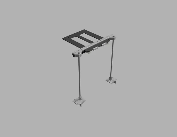
Simple, budget(-ish) and effective triple Z implementation for the ender 5 that doesn't block access to the front of the printer like pretty much every dual Z mod
I've done a speedboatrace on it with a corexy motion system @20000mm/s^2 here and the bed barely shakes (unlike my first speedboatrace attempt with just super struts)
What to print:
- I recommend printing full_set.stl since it has all the parts on one bed and orientated correctly to avoid supports. It is located in May 2023 latest version/full_set.stl
- There are also files for individual parts if you need just one of the parts
Features:
- Independent control of all 3 lead screws - if you add a stepper expansion board you can do Z tilt adjust(klipper recommended)
- Very rigid if you use a denser infill
- Uses original Ender 5 bed carrier and rear Z system
- You probably have most of the parts lying around anyways
Bill of materials:
- 2x NEMA 17 steppers - I used these and were the right length
- 2x T8*4 350mm lead screws and nuts
- 2x 8mm 370mm linear rods
- 8x M3*8mm socket head screws
- 2x 5mm to 8mm couplers
- 2x LM8UU linear bearings
- 10x M4*8mm socket head screws
- 10x M4 drop in T nuts
- Stepper motor extension cables - length depends on where your electronics are
Mods:
- REQUIRED Rear electronics case mounting
- EITHER Klipper and secondary motherboard OR daisy chain two stepper splitters
- RECOMMENDED rotate the heat bed 90 degrees anticlockwise so cable exits through the rear, zip tie the cable to the Z offset screw
Instructions for install:
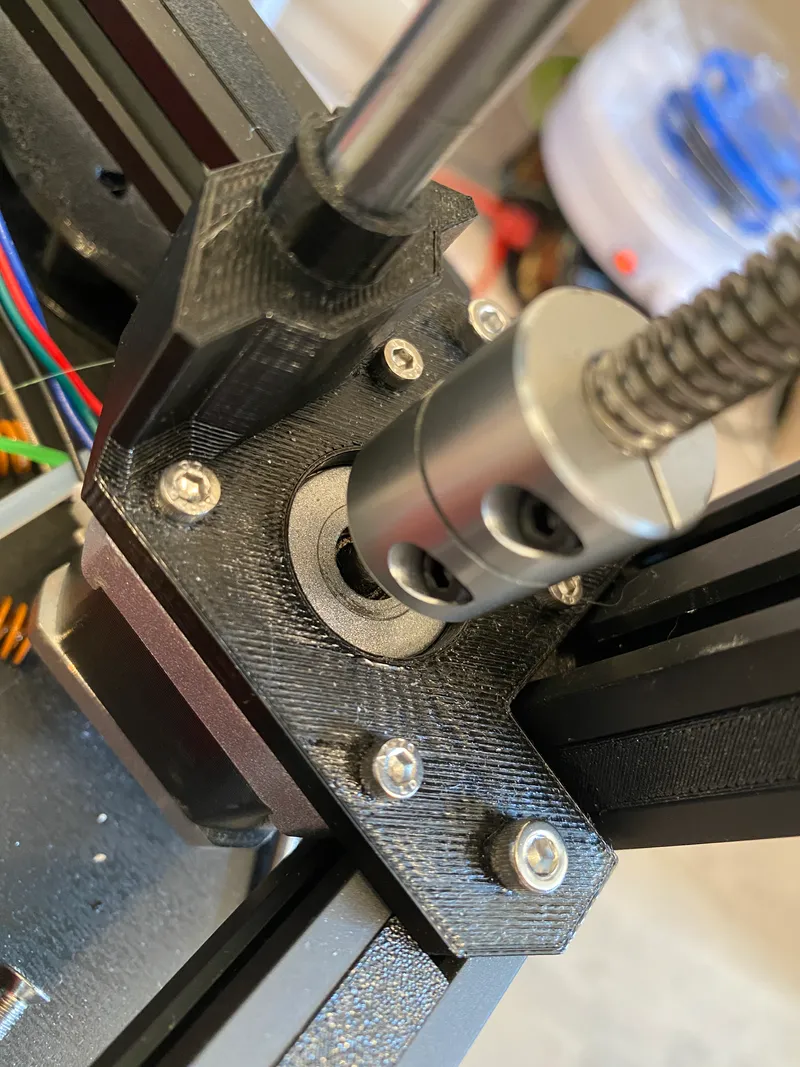
- Attach stepper motors to left and right stepper mount
- Attach both stepper modules to left and right front corners
- Insert LM8UU bearing into the bearing slots
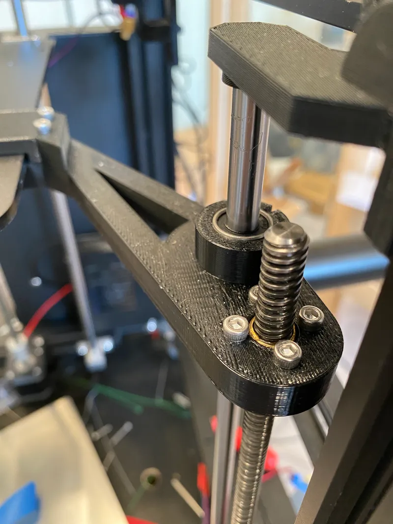
- Use 4 M3*15mm bolts and 4 m3 nuts for attaching lead screw nuts
- Detach bed cables
- Unscrew bed leveling knobs and remove heat bed
- Put left and right arm under bed
- Put left and right clamp on top of carrier, aligning holes
- Put 8 M3*35mm bolts through the holes
- Use 8 M3 nuts on the bottom sides, don't tighten all the way
- Insert the linear rod from the top down through the linear bearing into the stepper module
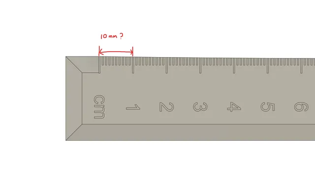
- Add the lead screw into the nut until about 5cm of it is below the arm
- Attach the lead screw couplers and tighten
- Keep rotating the lead screw until the coupler sits tight against stepper shaft
- Tighten 5mm side of coupler
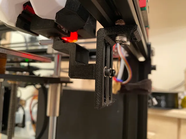
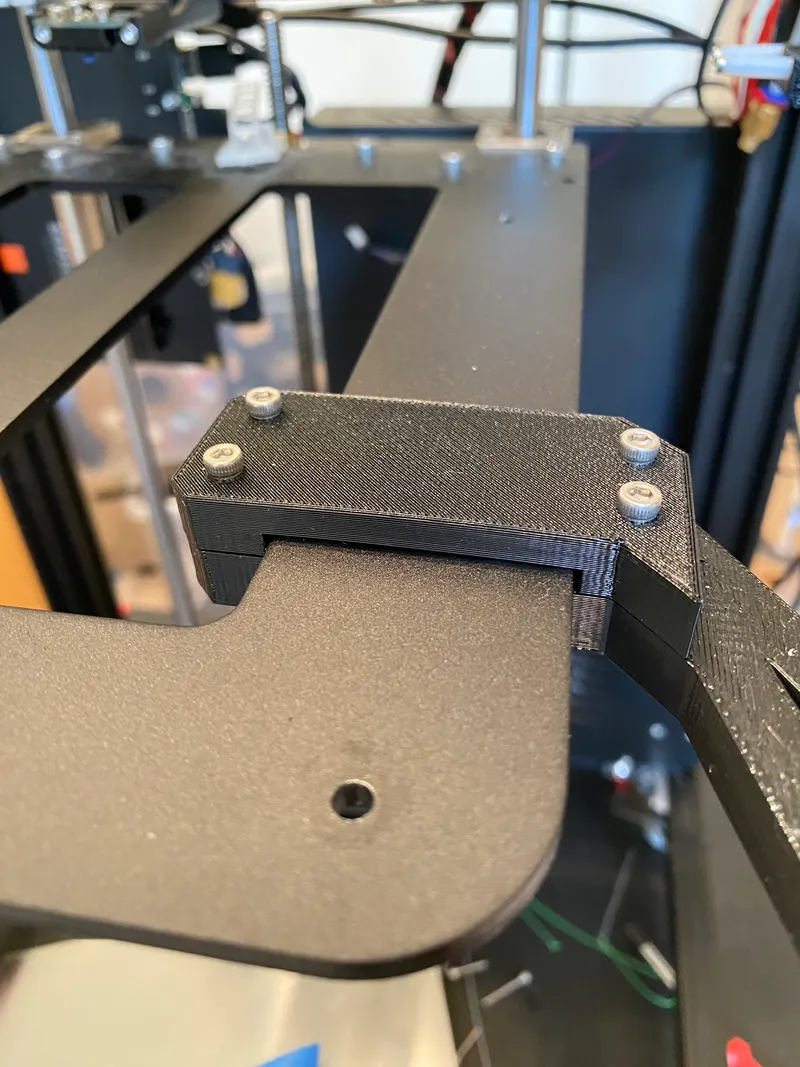
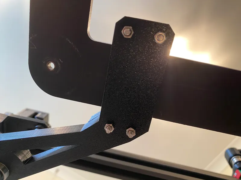
- Attach Z top parts - first load it with T nut and M4 bolt, attach to linear rod, rotate so nuts face the front extrusions and tighten bolts
- Tighten bolts on the arms
- Reattach bed and cable
- Move the bed to touch the nozzle in the rear back point
- Move nozzle to front left and rotate the front left lead screw so it also contacts
- Repeat for front right
- Plug in stepper cables
- Put some PTFE grease on the lead screws and run it up and down a few times
- (Recommended) Use these cable clips to tidy up wires
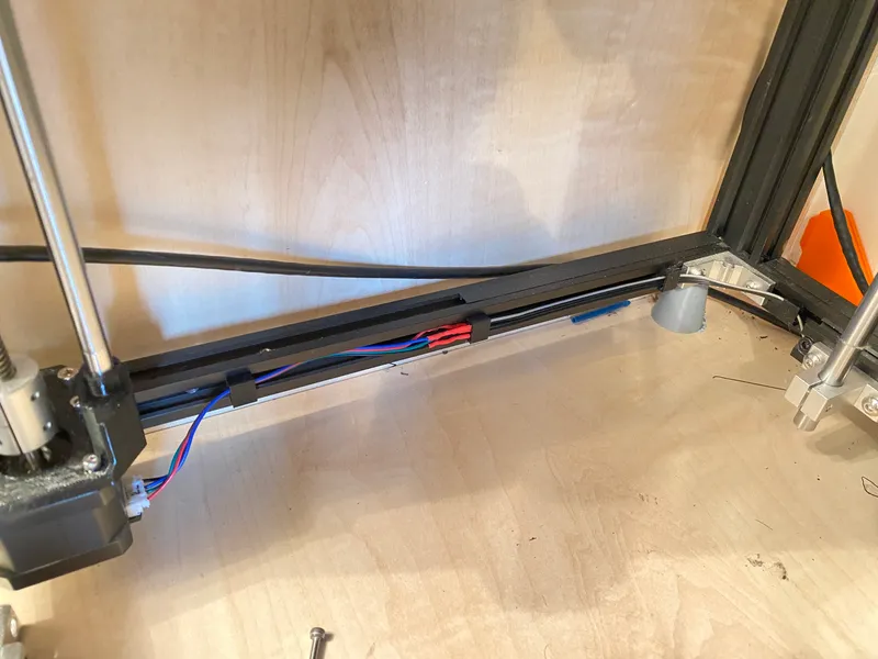
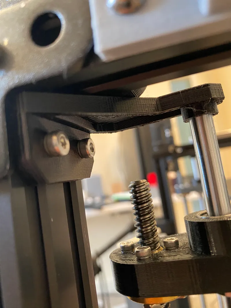
Photos for reference
Print settings:
- ≥50% grid infill
- 0.25 layer height
- 4-5 walls
- 6 solid layers top and bottom
- Recommended: PETG, 250 degs C
Tags
Model origin
The author marked this model as their own original creation.