MMU Large Arch with stand for PTFE spacer tubing

Description
PDFThis item is no longer needed in my larger path design - https://www.printables.com/model/555238-mmu3-filament-path-design
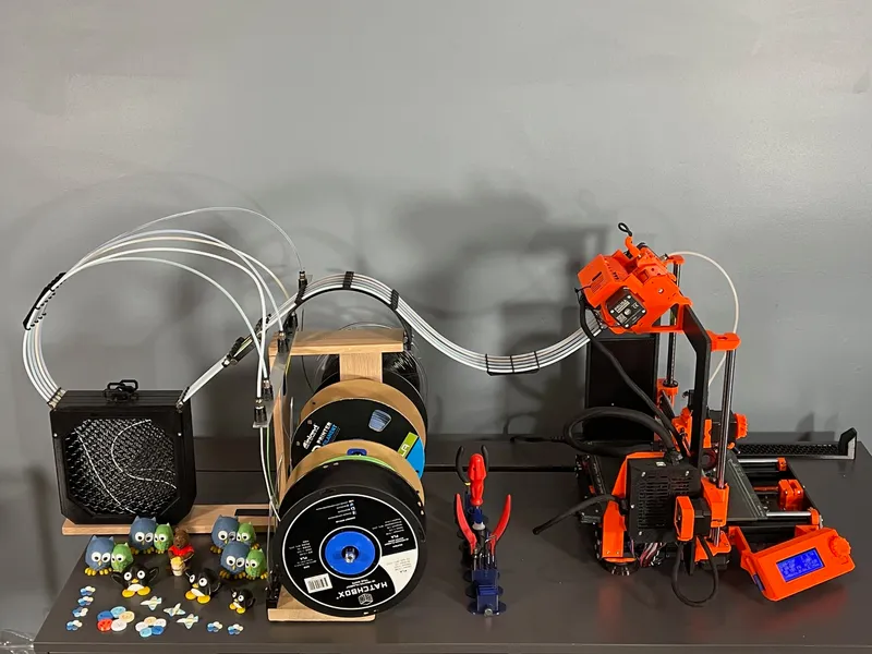
TLDR - This makes your filament path look like a rollercoaster, but it is actually the most important functional part of my entire MMU system when I use it with polyboxes by adding an evenly placed amount of static friction over the filament path after a retraction, which holds it in position over the idler gear for the next use! Also look at this which is a better option if you are not using a polybox.
What is the problem? - load errors mostly
After a filament retraction, the idler gear releases its grip on the filament and the filament waits to be used again. It needs to stay in position hovering just above the idler gear so the idler gear can grab it the next time it is needed.
If the filament moves backward even a centimeter the idler gear cant easily grab it, and you get a load error at worst, or grinding and then a load at best. But even if it grinds you will eventually have a failure due to filament dust on the idler gears which will eventually cause a load error and require an air blast as well. If the filament slides forwards even a few centimeters and sticks out a little from the short PTFE tube it will block the selector from moving and you get all red blinking lights and have to reset the MMU after pushing the filament back end. I had both of these errors many times until I made this part.
How often does this happen? - about once an hour
This filament slipping problem can occur never or very often, depending on the filament type and how easily it bends. I found it happened in about half my spools and about once every ten or so changes, so about once every 20 minutes to an hour, depending on the print. I had to babysit the MMU. I knew how to fix these errors but it became tedious. Many people claim only a few brands of filament work with the MMU, and this is why, but they are wrong. I am now able to print with any brand, even rough matte or slippery types.
Why does this happen ? - filament comes curved on a spool
What would cause the filament to move backwards or forwards after a retraction? The problem is that the filament came wound on a spool and has inherent bends and twists, and is under internal stress to curl back on itself. This tension is unpredictable and happens more in some spools than others, and can manifest in sliding backwards or forwards.
How can filament move, isnt is locked inside a PTFE tube?
The filament tube inner diameter has to be a little larger than the filament diameter, so the filament can fit inside the tube. This small space around the filament allows the filament to make small bends all along the length inside the tube, and these internal bends can affect where the tip of the filament ends up at the end of the tube. The filament is always the same length, but by bending around inside the tube less or more or the tip emerges at the end, at the idler gear.
Why an S shaped filament path? - to place even forces along the path
The goal is to hold the filament just before the idler and above the idler gear in position but not too tightly. This hill, if used with the length and arrangement as shown in the photos before the MMU, adds a "S" shaped curve between the buffer the the MMU. Since it is “S” shaped there is an even amount of force from the PTFE tube walls in upwards and downward directions, so there is no net force pushing the filament in a particular direction, and these curves cancel each other out. If only one curve was there, the forces from the PTFE tube would not be even and the filament might find a way to bend unevenly, affecting the eventual location of the tip. The force of these two curves adds evenly distributed static friction against the filament from an upwards and downwards force and this friction gribs it just enough to prevent it from slipping once the idler gear lets go it it after a retraction.
How does S shaped path compare to other filament paths? - it is the best
A long straight tube allows a lot of internal movement and wont work well. A long tube with a single curve adds uneven forces and can be unpredictable.
An air buffer (no tube) combined with a short rear MMU tube allows the filament to move as it wants and not effect the tip position, but the problem is that there is very little PTFE tube surface area holding the filament in place near the idler, which is a different cause (too little friction) but results in the same problem, a load error due to the filament moving around the idler after a retraction. It is a very delicate balance to add just the right amount of friction to each filament tube independently, and would have to be done for each print with some screws manually for each line, which opens up a lot of error possibilities. And an air buffer also adds the problem of the filament kinking in the air on itself. An air buffer could work if these two variables could be controlled, but that is hard to do.
Design goal - remove friction everywhere except the S curve
In my system this is design goal, to remove friction everywhere except this S curve, and I even go as far as a custom spool system to remove friction on the spools as well and use a non mechanical slot buffer which is amazing. I used to use a polybox and sit this on top but that added a little too much friction in the spool system so I swapped that out for a custom spool system and rack to support this arch. I believe this is the best setup but using two polyboxes worked well too and removes all the wood and spools but is more expensive. Most of the the other parts of the setup I also designed and are in my “Used on MMU” collection.
The small black optional part between the S curve and the slot buffer has an open area to ‘feel’ the filament loading in the idler, but is really nice to have. You can also feel the tension on the filament as it moves here. This is an older pic below but shows another possible layout. I now have improved this. See the doc and setup for the coupler part where that is written up.
What to Print:
This is in two parts, an arch and a base. You might not need the base. I made the base mostly for spanning two polyboxes, but a later design has this attached with screws into a wood riser so the base is not needed.
Print both parts and screw together with 4 spare 16mm m3 hex bolts and 4 nuts. This is a large stand that has an arch on top to route all five of the MMU PTFE tubes. See the pic of how I am using it in my setup. I have it on top of two polyboxes between a slot buffer and the back of the MMU. The curve adds some needed friction to the tubes to prevent the filament from sliding out the back and prevents the tubes from twisting. The PTFE running though this has 2mm inner diameter in order to control retraction tension/spacing within the tube. All the other PTFE tubes in my setup are 3mm inner diameter to reduce friction everywhere else and prevent snags, including the small tube inside the MMU and the one going to the extruder.
Other parts of the setup have an open coupler adjuster for the PTFE that allows me to connect two types of PTFE diameters (3mm and 2mm) together and provide a manual place where I can adjust/push it. The polybox position functions as a needed foundation for this arch. The filament path is about as compact as needed with enough areas to retain the filament position within the tube from static friction. The slot buffer sits between the drybox and the coupler/adjuster.
I wrapped back electrical tape over the ends so as not to scratch the polybox.
See my collection called MMU upgrades in use to see all mods I use, this being one.
Tags
Model origin
The author marked this model as their own original creation.


