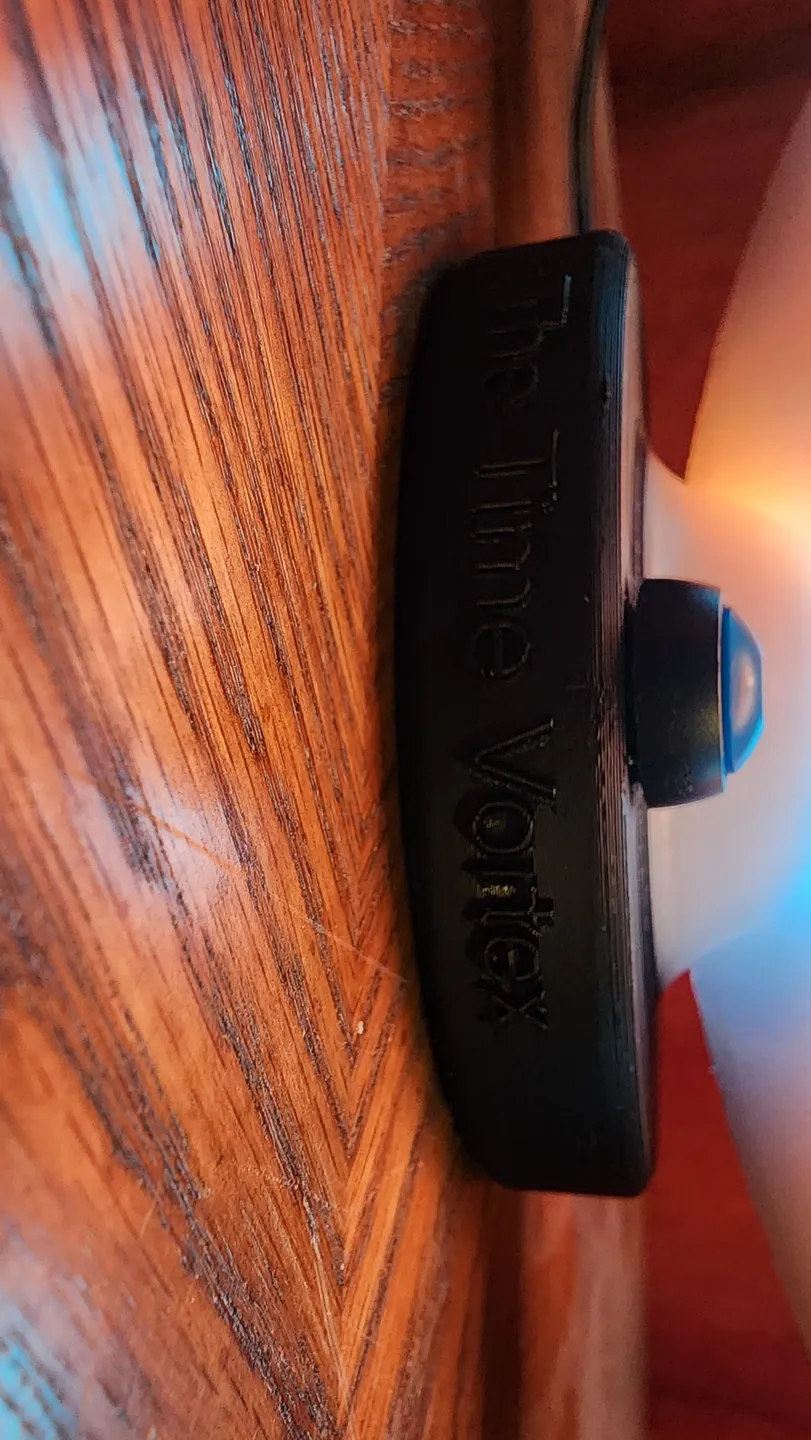
The Time Vortex


Description
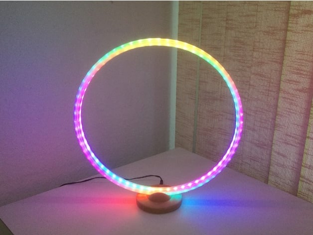
PDFThis design was inspired by the excellent ring light by geit_de: https://www.thingiverse.com/thing:4904677
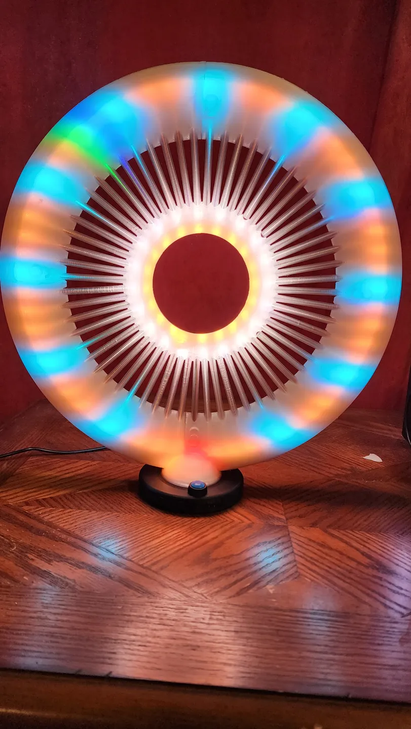
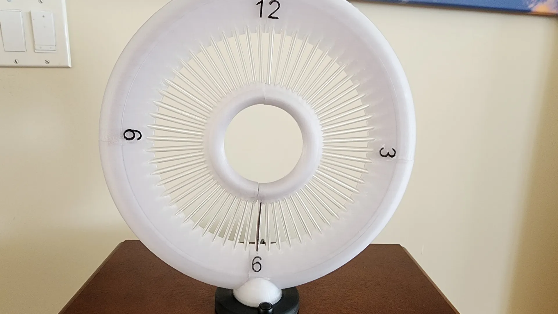
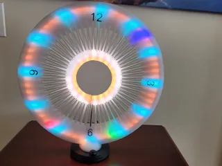
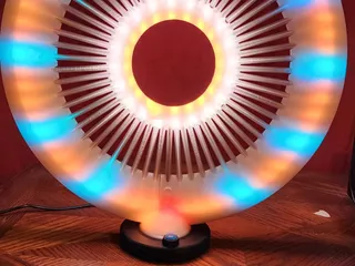
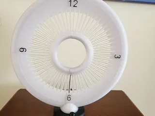
I liked the dual led strip lighting effect, and decided to design a WLED based led clock using a centre ring to get a “floating” effect.
Warning: you need both soldering skills and patience to make this project.
Both LED strips are placed inside channels within the large and small ring sections. The electronics are completely in the base.
I have provided a 3mf file for the bambu printer, as that is all that I have.
Key Features:
When designing this I had some key features in mind:
° Create a dual lamp/clock
° Use the excellent WLED program by aircookie: https://kno.wled.ge/ which adds a configuration and control web page.
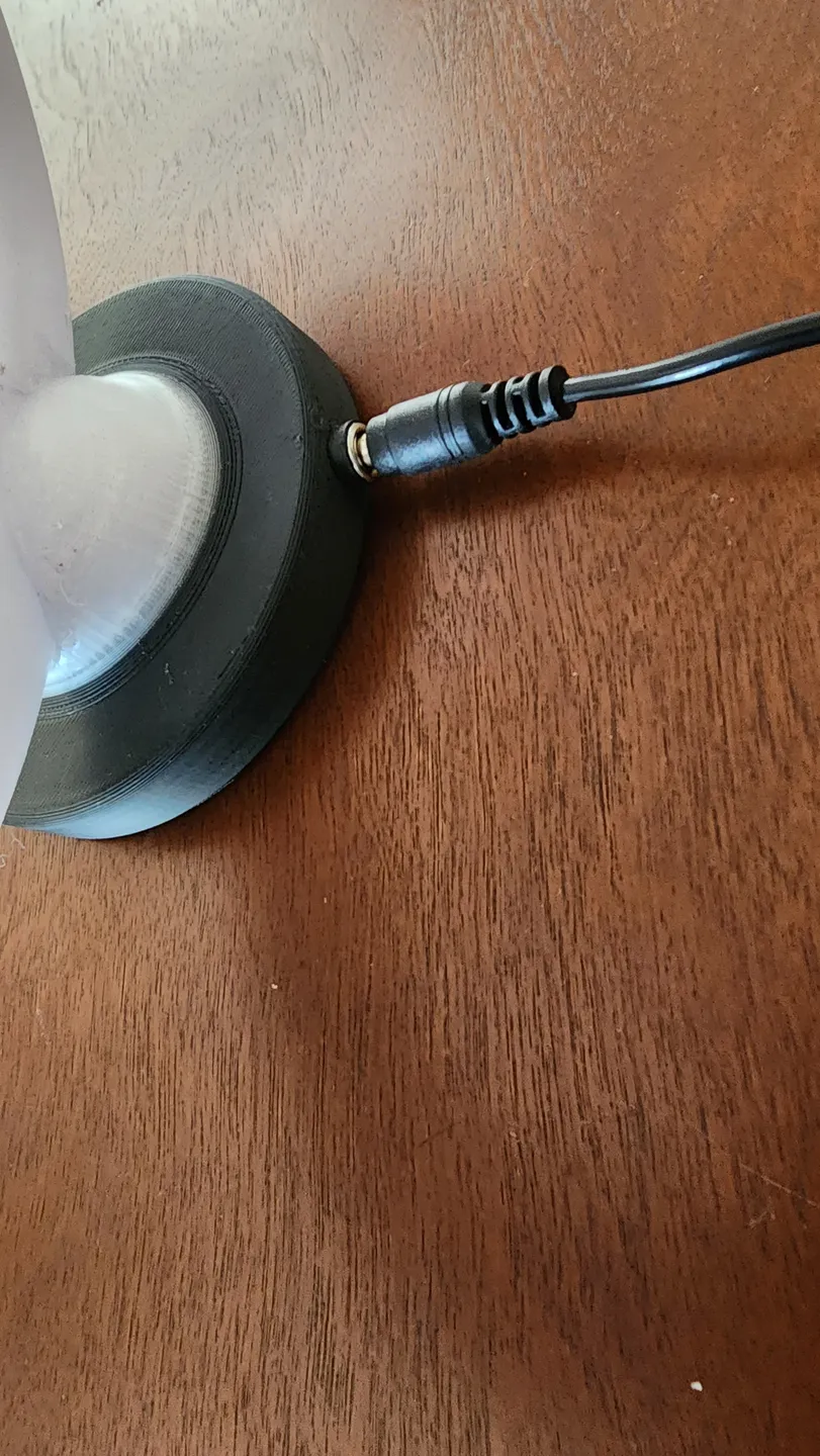
° Add a base to house the electronics.
° Easy wire management
° Easy to print.
° Create a “floating” centre ring effect
Requirements:
- 5V power supply. 3amp is recommended, but 2 amp may be used if lower brightness is acceptable. VERY IMPORTANT: BE SURE TO SET THE CURRENT LIMIT CORRECTLY IN THE WLED CONFIGURATION TO AVOID OVERHEATING!
- Power Connector
- Switch
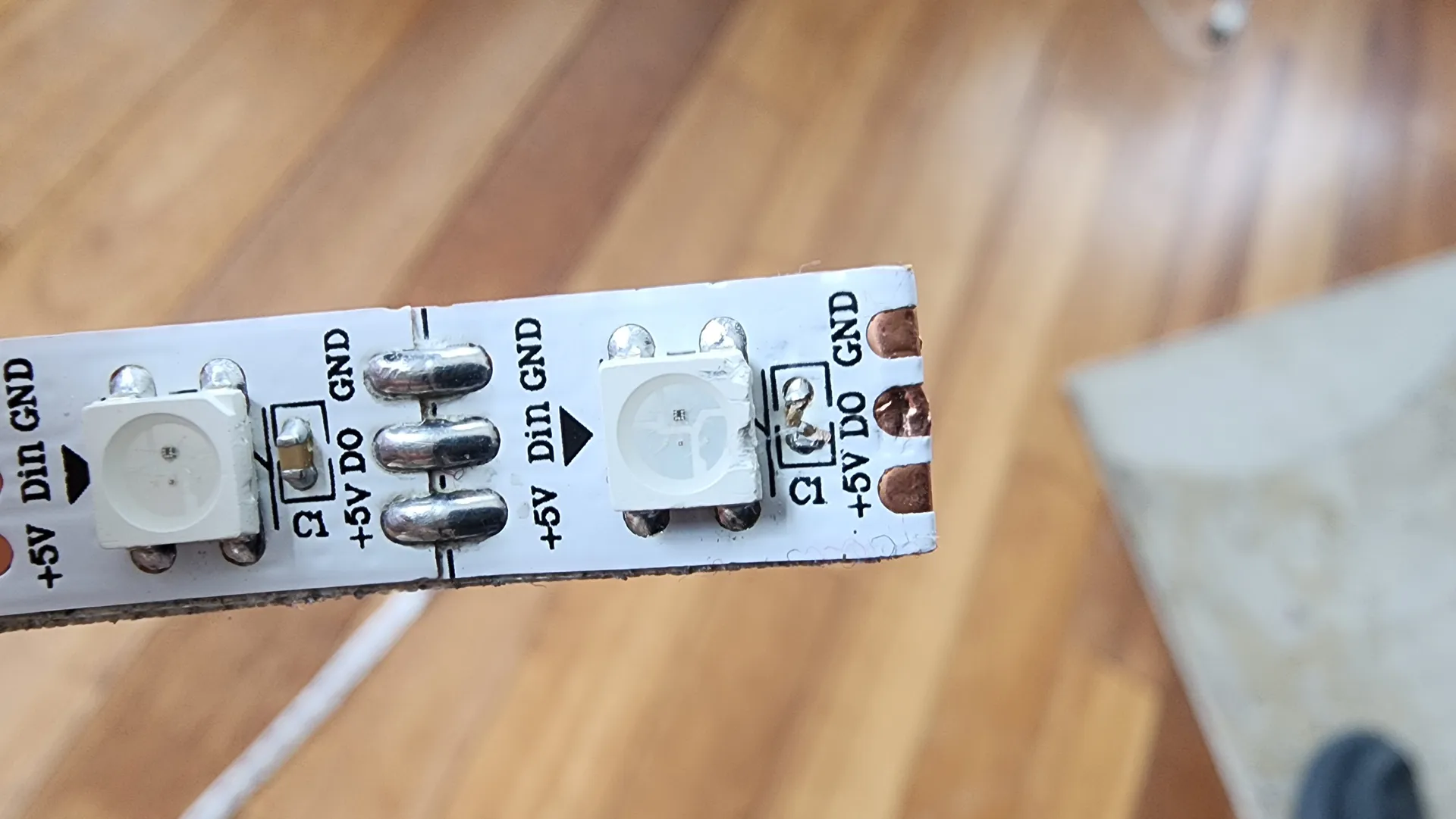
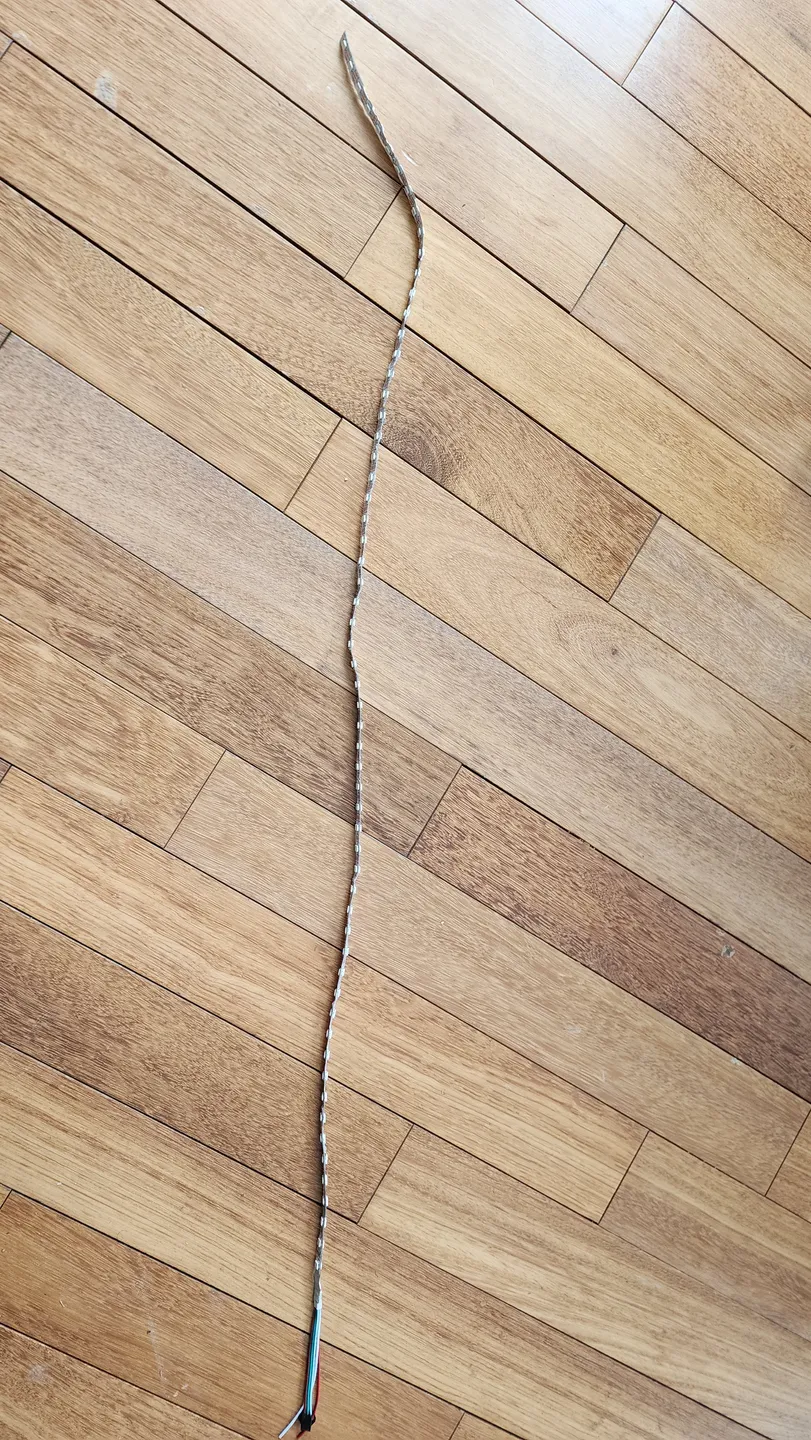
- Two LED strips (60 pixel/m ) 120 leds length and 40 leds length respectively. You need a LED strip without a rubber dome. Just the plain flexible PCB with the LEDs and resistors soldered on. ie like: https://m.aliexpress.com/item/4001249438672.html?spm=a2g0n.order_detail.order_detail_item.3.56f4f19cTzFJVa
Printing:
Use clear (natural) or transparent PETG or PLA. I used esun natural PETG.
Print the base and lid in black, with a layer based color change to clear for the top of the base.
You need to print a the socket, the lid, the diffusers,two small inner ring sections and four outer ring sections. One of the outer ring segments has an opening for the wiring. Use a raft when printing the ring segments and use tree supports. Use supports on the base as well.
Step files are provided to allow for easy customization and accurate printing.
The outer ring is identified as ring1.step to ring4.step and the inner ring is identified as centre1.step and center2.step.
The diffusors need to be printed in vase mode to make them hollow. I find I can print 5 at a time on the bambu by arranging them on the diagonal of the build plate. Similar results could be achieved with prusa machines. 60 diffusors, one for each second, are required for the clock.
If you find making the diffusors too time consuming, you can make just the outer ring. I have provided ring1nh.step-ring4nh.step for that purpose.
It is important to print the rings with 100% infill . This provides the best light diffusion effect.
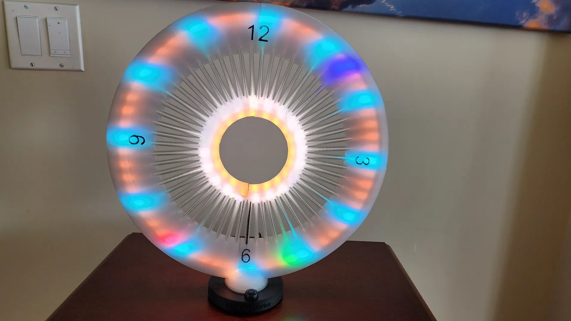
After printing, you can paint the 12, 3, 6, and 9 numbers on the rings using black paint. (or not, if you are happy with them being clear)
LED CHANNEL CLEANING:
Before starting the assembly, you need to ensure each LED strip opening is free and easy to fish the led strip through. one way to do this is to pull a wire through each ring section and make it rattle on the inside to ensure there aren't any printed blobs or walls from stringing blocking the channel.
Pro tip: If you have a faulty strip of leds that you can run back and forth through the channel, this will do a great job of clearing/smoothing them out. I personally sacrificed a short double row of leds to be used for this purpose. It makes fishing the good leds into the rings a LOT easier if you clean out the channels well beforehand.
It is a good idea to test the LED strip using WLED before fishing the led strip into the clock pieces. For testing, setup an esp processor to on a breadboard and log into the WLED web interface and turn the leds on to one of the wled presets. Confirm that every LED is responding correctly. If not, you may have to cut the broken LED out and resolder the joint, or start with another strip.
Clock Assembly:
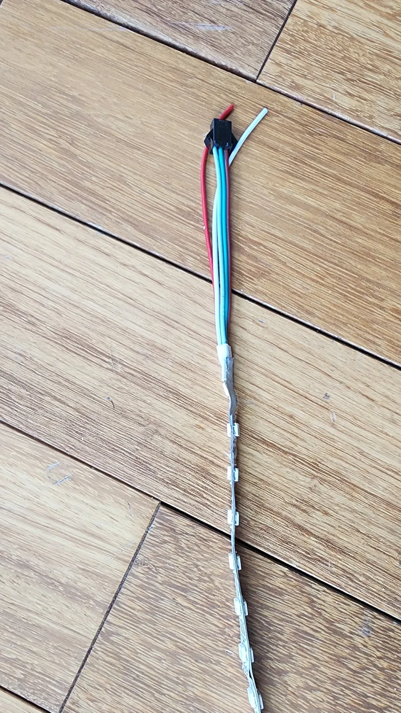
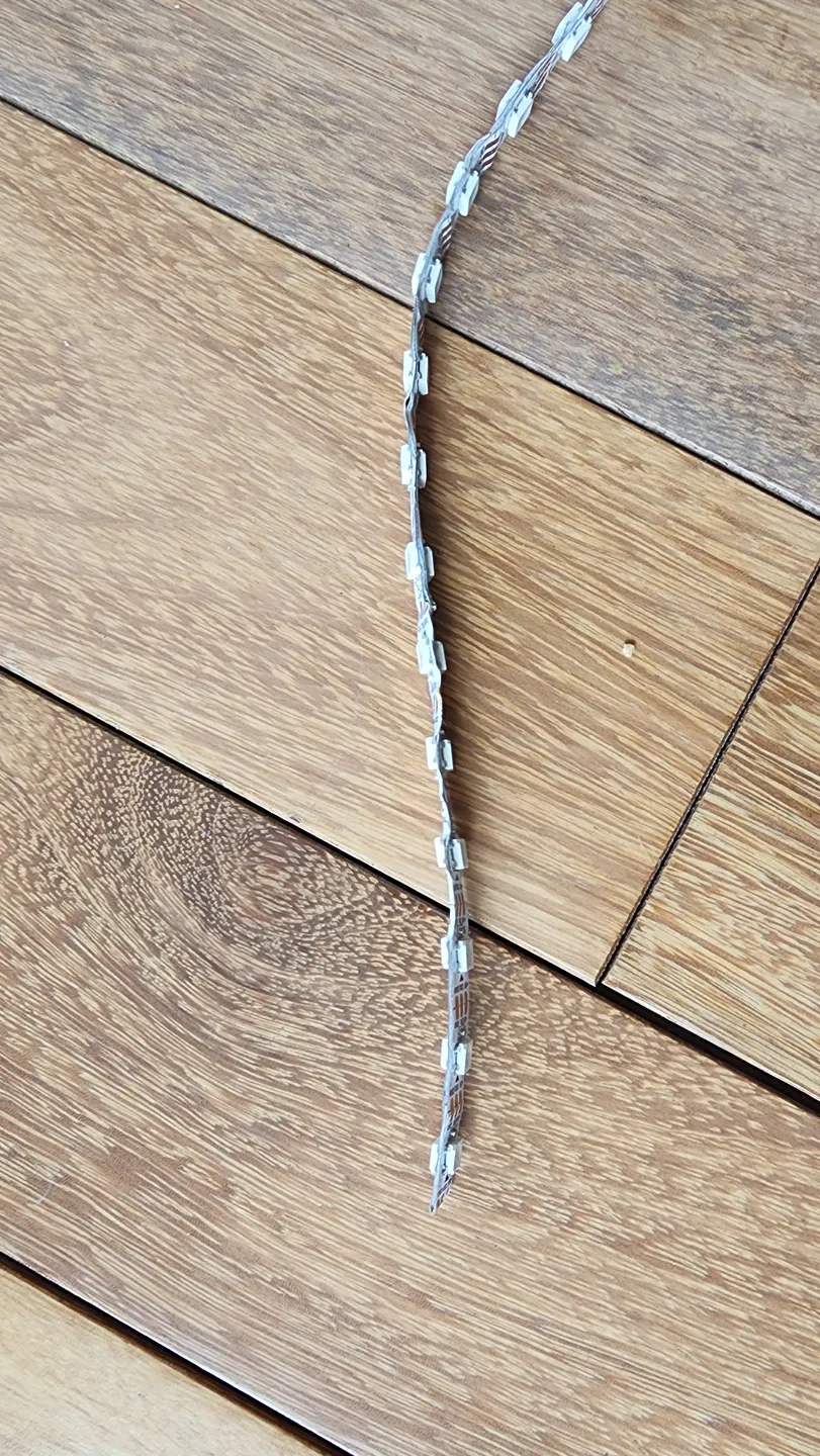
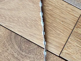
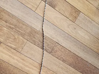
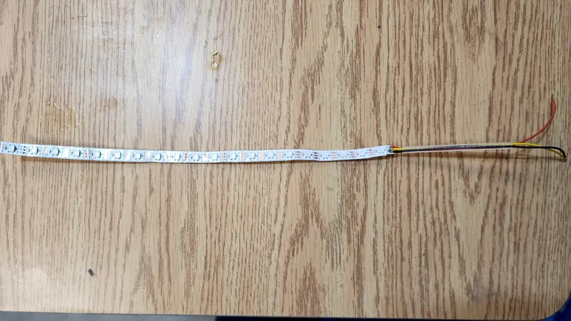
Prepare two bouble sided led strips, one with 122 leds and one with 40 leds. Remove the sticky tape from both LED strips, find the middle of the strips , fold them over and push them against each other. Make sure you get them lined up on top of each other all along the tape.
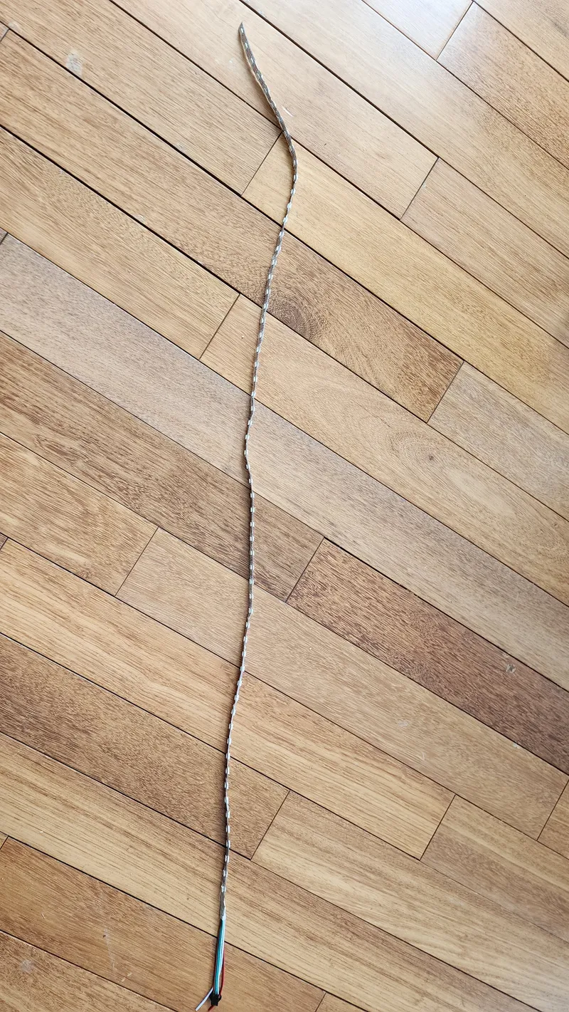
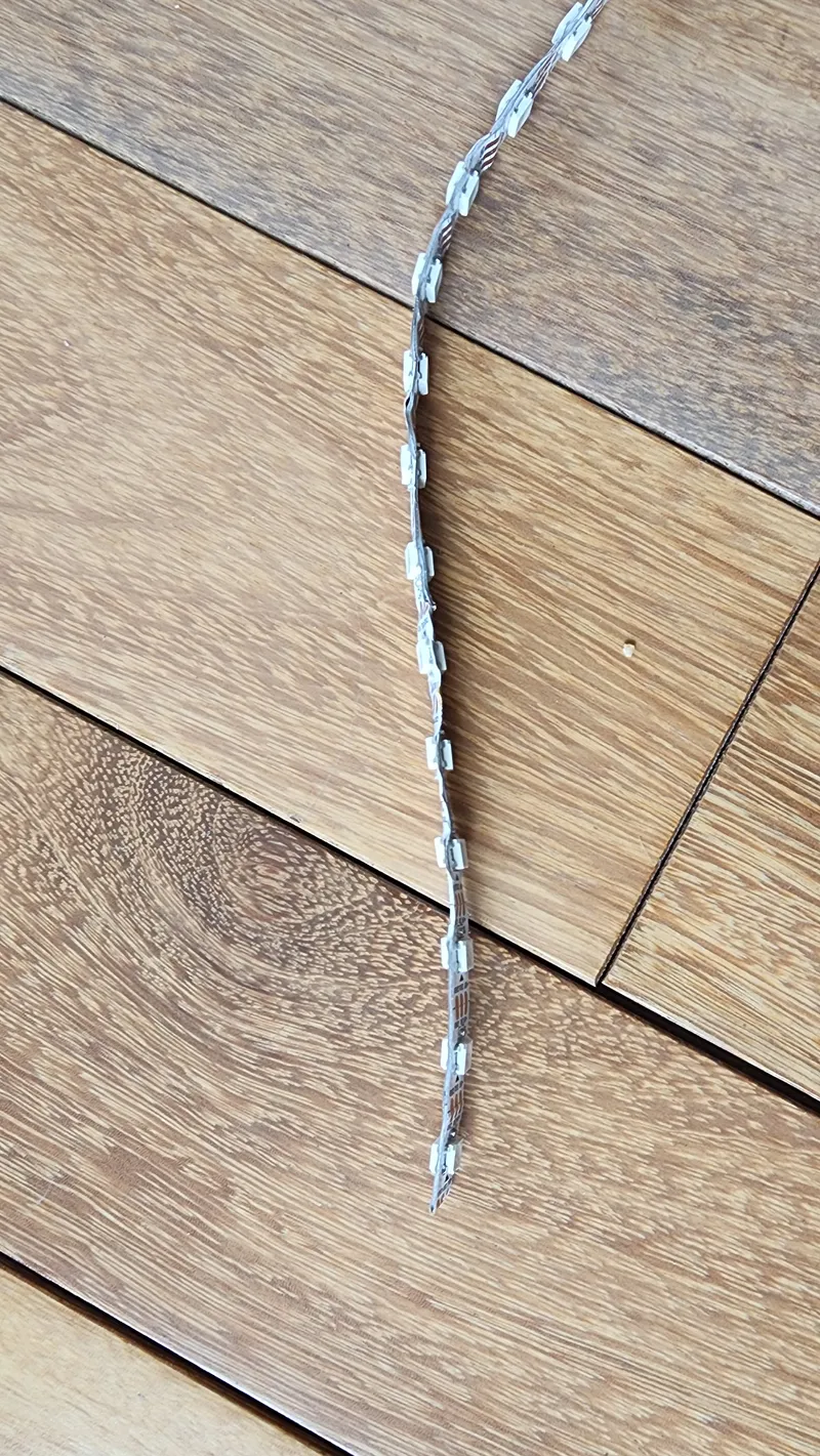
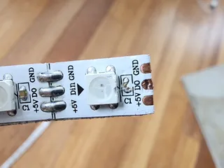
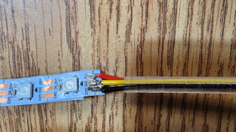
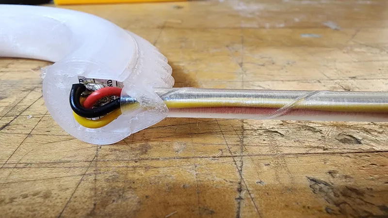
You can solder 8 cm wires to the BEGINNING of the 40 LED AND 120 LED strips now. It is important you solder the data lines to the side where the arrow point into the strip. Also solder 8cm wires to the end of the 122 led strip. This will make Connecting the center ring easier later on. The wires will be together on top of each other for the 122 led strip
40 led strip with diffusor:
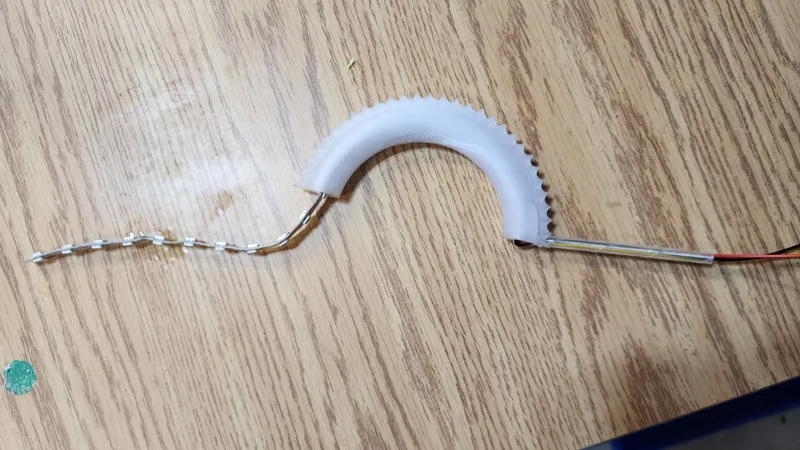
 Fish the 40 led double strip with diffusor through one of the centre sections as shown:
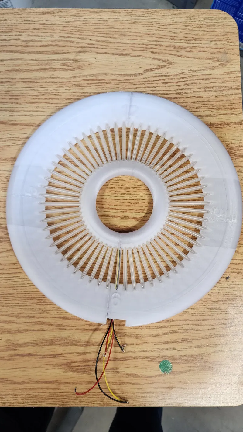
Now, fish the 122 led double strip starting with ring1 of the clock.
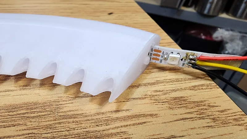
Important: The first 60 leds are for the clock face. The strip must be oriented so that the first leds are facing the inside of the ring as shown below. This will ensure that the clock is displayed on the inside of the outer ring
 Continue fishing the led strip through the remaining rings, ring2,ring3 then ring4.
You will have a loosely connected ring on the table. Ensure that the leds are lined up with the openings and using a little bit of super glue the segments are quick attached together.
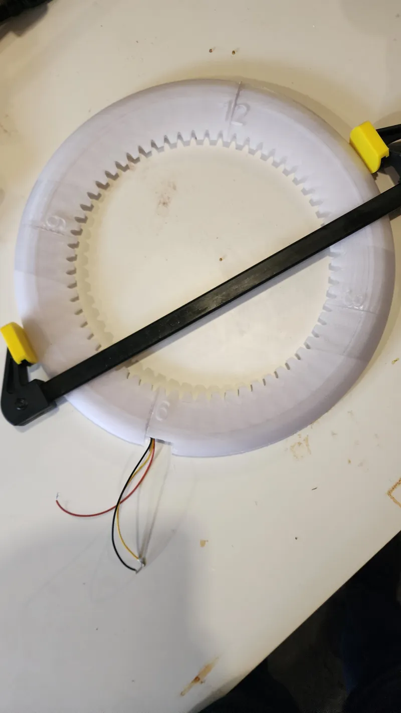
Take your time and let the glued sections harden overnight before moving over to the next section. If you rush it just gets messy very fast. Repeat the gluing step. It is the best to glue the bottom right section to the 3/4 ring last. Make sure the wires are in position, put glue on both ends and press the rings together. You can optionally use a clamp to hold everything in place during curing:
When the ring is done and fully cured you can do another WLED test run on both rings to see if the LED strip survived.
Now, you can assemble the clock with the inner and outer rings.
To do this, first push the led diffusors into all the opening, leaving the 30 second opening free for the centre ring:
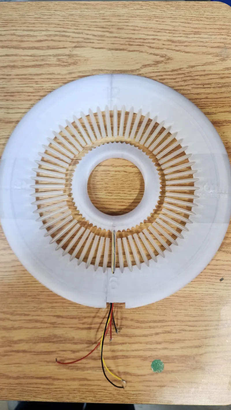
Add the centre ring at the 30 second opening and insert all the diffusors into the inner ring:
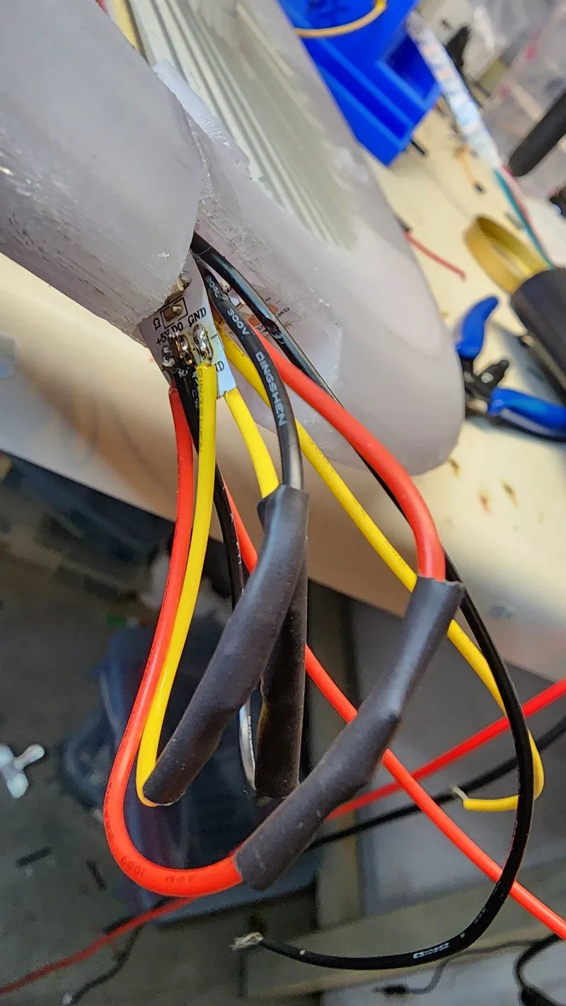
Connect and solder the inner ring 5V GND and data wires to the wires at the end of the 122 led strip as shown:
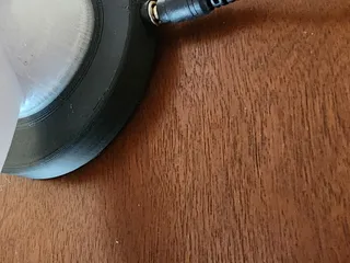
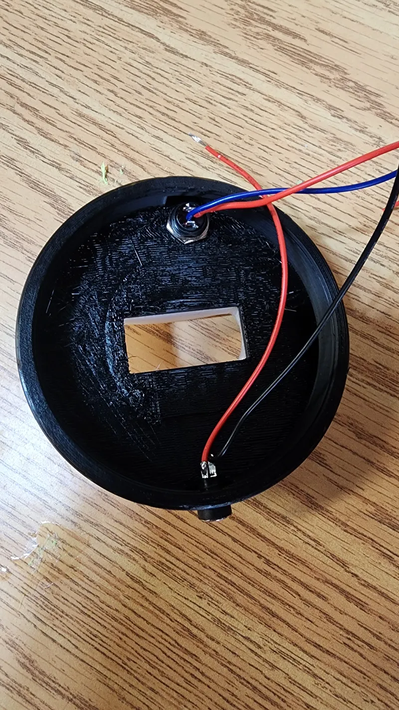
Slide in the switch into the socket and secure the power connector in place.. You can solder both components after mounting them, but I found it easier to add the wires before ading them to the base.
Feed the GND, DATA and 5V wires into the base and glue it on.
You are now nearly done.
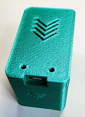
now it is time to add the processor.
either an esp8266 or an esp32 processor could be used
Connect the processor to your computer and program it for your wifi using this site:
https://wled-install.github.io/
using the provided cfg.json and preset.json files restore the configration and presets to the processor.
Connect all 5V to 5V, all GND to GND and the ring light data line to GPIO2 (D4) of the ESP. The two switch pins need to be connected to GPIO1 (Tx) and GND respectively:


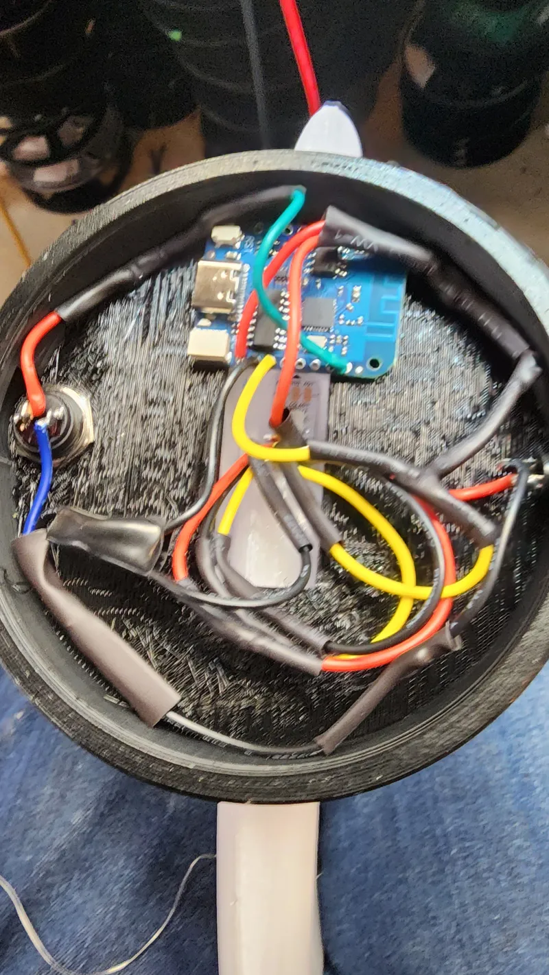
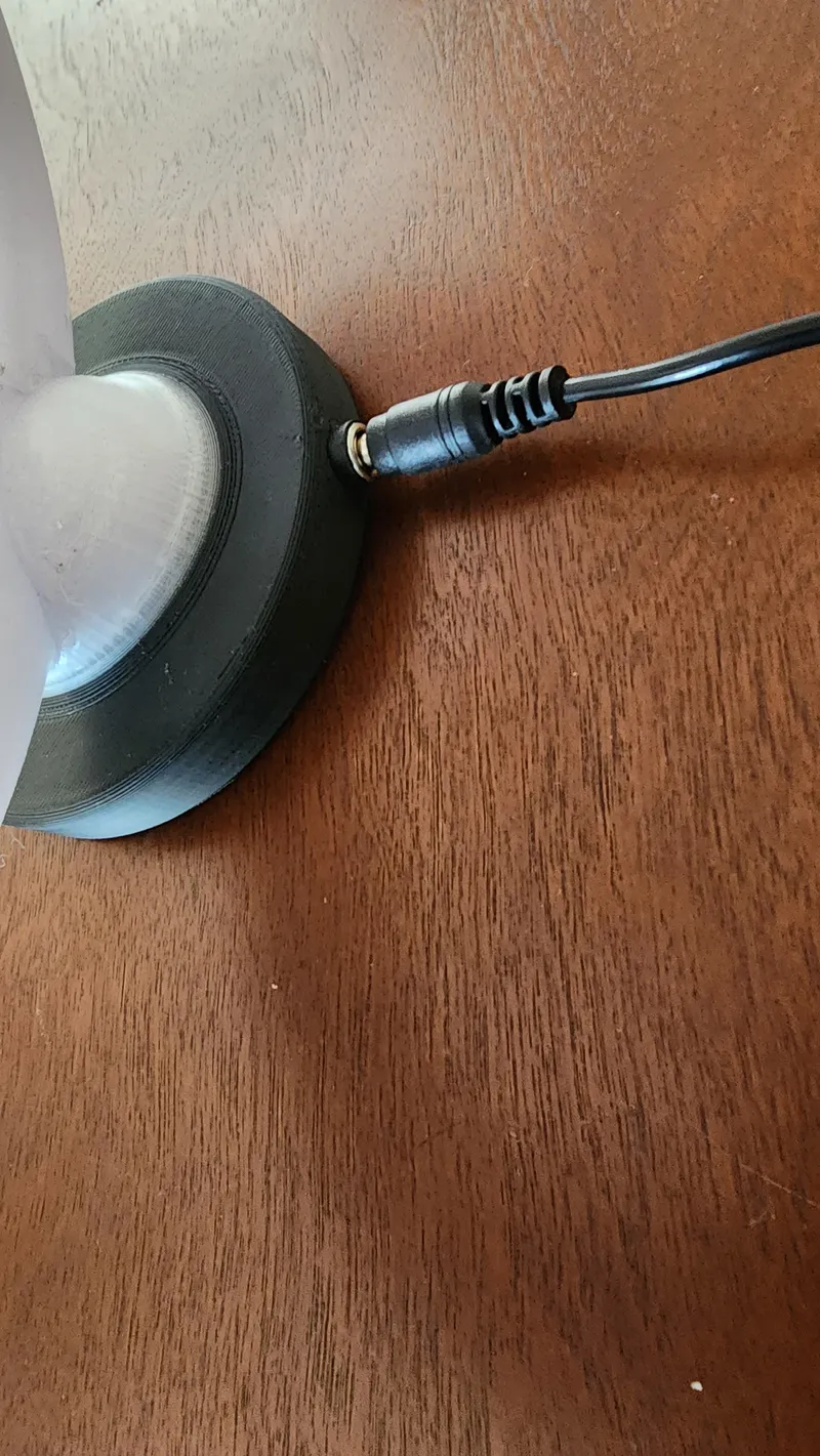
Add the lid to the base and connect the 5v power:
All Done. Congratulations!
Current Features:
- web interface
- OTA update support
- playlist for cycling through the presets
- 69 effects (static, rainbow, fire place, RGB fader, ...)
- single button press to turn lamp on and increase brightness
- double press button to set half brightness
- long hold button press to turn lamp off
- timed power mode: The ring lamp turns on and off at a specific hours.
Although I provided a playlist and presets, all led effects are completely customizable using WLED. Feel free to design your own presets and clock face!
Final Comments:
If there are any questions feel free to write a comment. Please post any makes; I would really like to see your results!
What follows are some short videos illustrating the clock operation:
Basic Clock face:
Playlist operation showing three 20 sec presets with two 10 sec displays of the basic clock face:
Some examples of various presets:
Tags
Model origin
The author remixed this model.