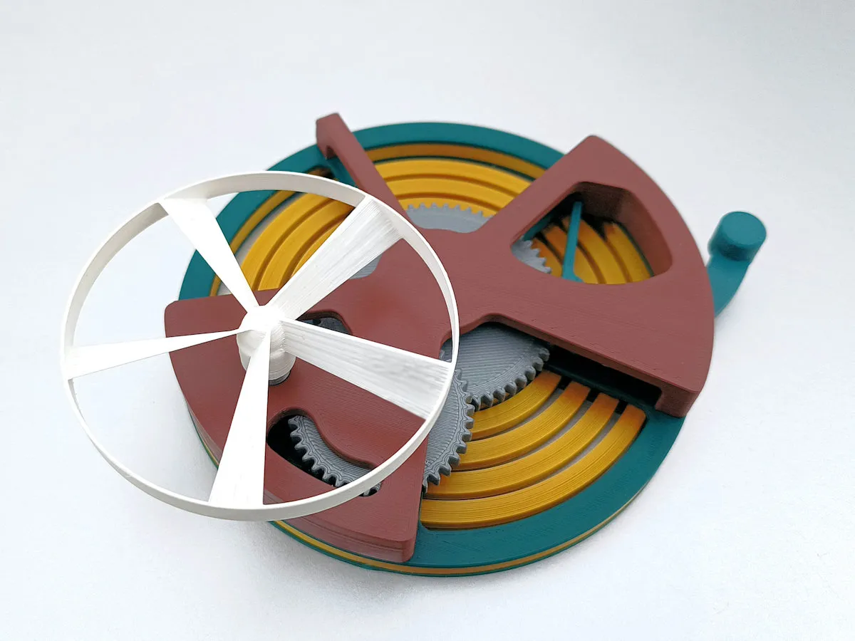
Propeller Launch Base


Description
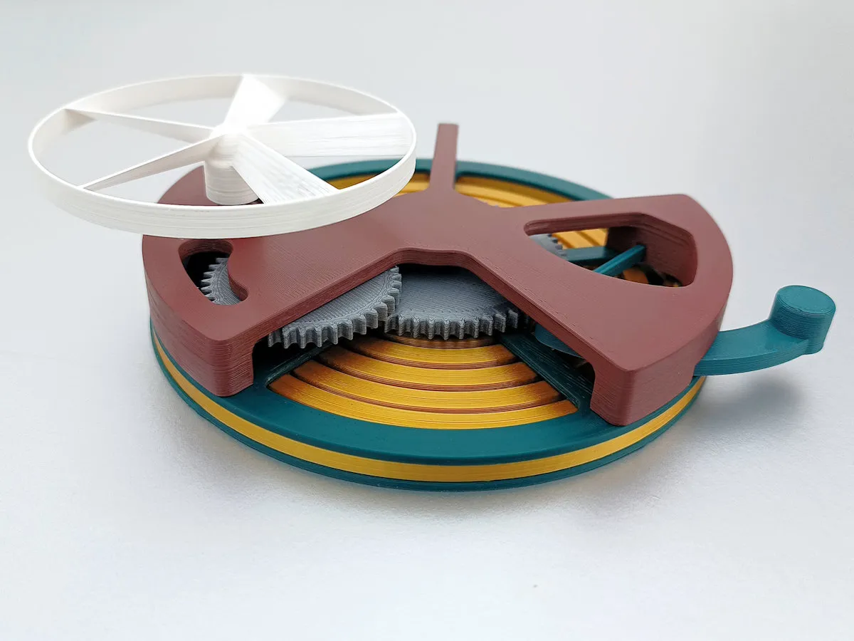
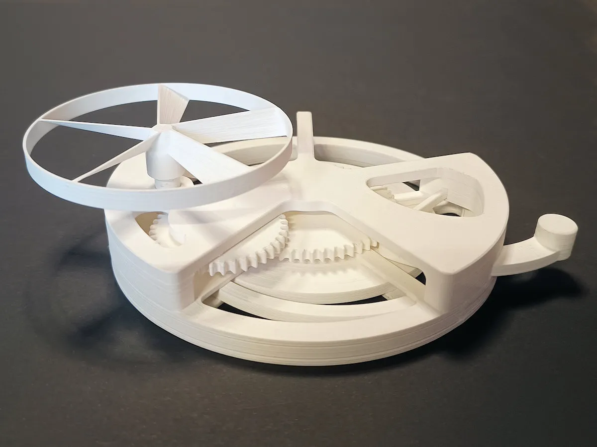
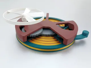
PDFLaunch your propellers using this mechanical marvel instead of a rip cord.
For the standard coupling I used the square coupling (same as Meister Edel did). To possibly create other coupling mechanisms I have added a stepfile of a coupling piece that can be used to place other couplings on top of the drive shaft.
I have done tests with various propellers. Best performer yet: A remix of Harald Andersson's propellor with the square coupling, created using the core piece provided by Meister Edel. See remix: Advised Propeller (for use With Propeller Launch Base). (this is also the propeller of the video).
Because the construction can launch a propeller in a repetitive manner, this design can be used very well as a test bench for the design of new types of propellers.
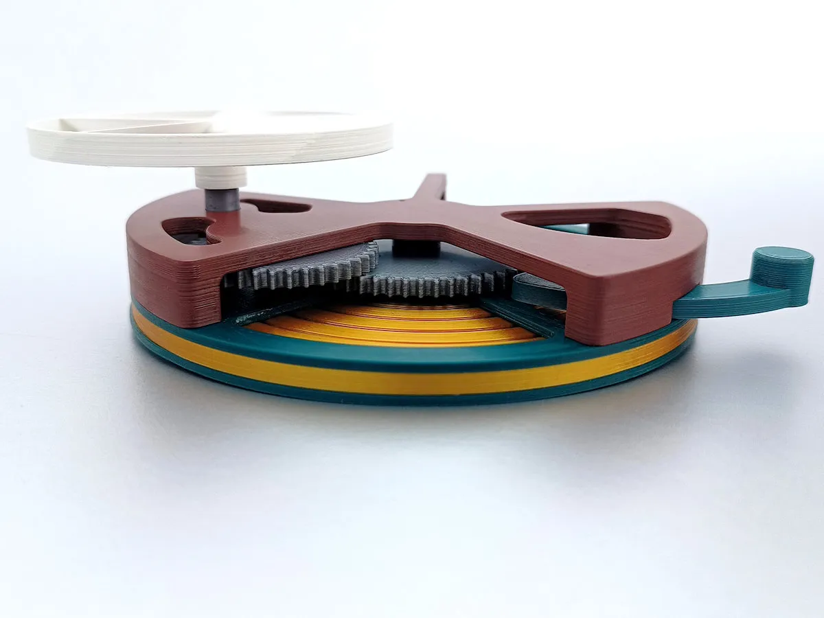
Winding can be done with the propeller itself. The forces are small due to the large transmission ratio, so that the propeller will not break quickly. If the propeller is too thin or fragile, the special Winding Knob can be used. (you can also use Gear 2 with your thumb, but after a while your thumb gets sore)
The design is based on printing with 0.4 nozzle and 0.2 layer thickness (also 1st layer!)
To ensure that all foreseen clearances are achieved correctly, I therefore recommend not to deviate from this.
I have kept a standard filling of 30%.
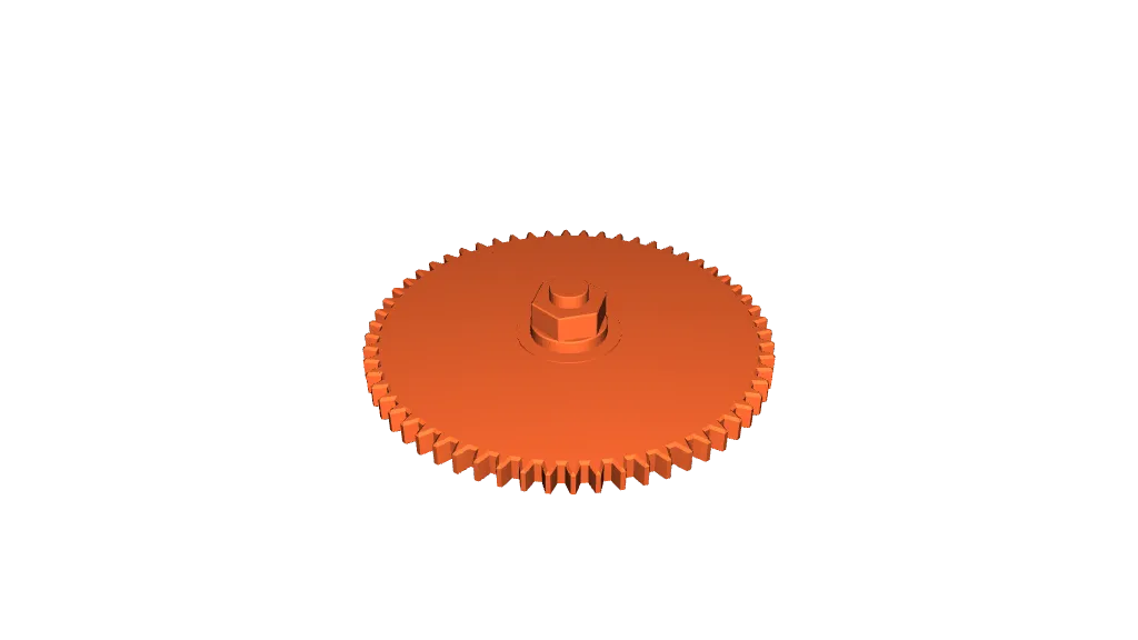
For Gear 2 I have kept 6 perimeters (standard 3) to ensure that the strength of the hexagon is sufficient to absorb the (extreme) spring tension.
For the Driveshaft I used an infill of 100% for maximum strength.
For the Spring Ring I have kept 6 perimeters to ensure that it act as a proper spring. * The print lines becomes shifted for each layer, this is by design to prevent tearing of layers!
All printed in PLA, and all parts without support.
For the spring and gears I recommend not using other than PLA, because PLA has the highest stiffness.
Update 29-03:
I realize that not everyone prints the same. When I print a hole Ø6, together with an axle Ø6 they fit perfectly tight. After wearing in by moving around in dry condition (this really makes a difference!) the printed sides wear off a little and creating an almost backlash-free run-out.
Based on feedbacks from makes I have added 2 additional sets of gears, with more clearance on the axles. Together with a testset, so you don't have to print the whole gearset to test.
For functionality: the tighter the fit (with free turning), the smoother it will run!
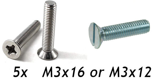
For assembly you only need 5x M3x16 or M3x12 countersunk bolts.
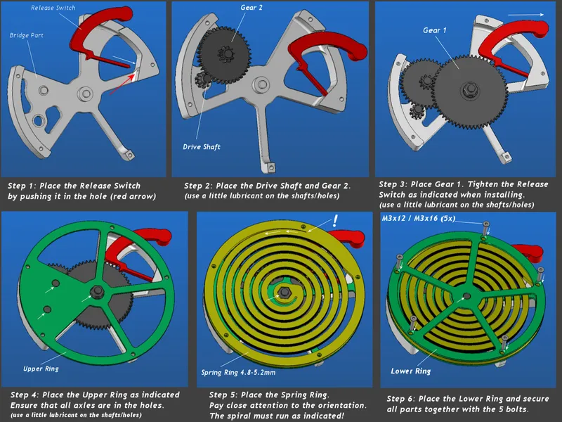
Assembly
- Put the bridge part with the flat side on a table.
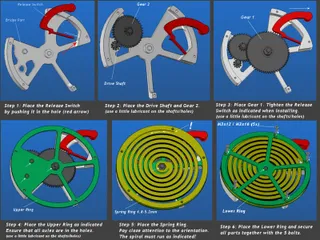
- Slide the Release Switch in the hole provided. The round button should be outside (see photo. This is a tight fit, try to press straight in the hole so the small part does not bend. If it's too tight use a knife to scrape off a little. It should be a tight fit when mounted. If it is loose in the hole, secure it with glue.
- Apply a lubricant (I used Vaseline) to each pivotpoint for the gears.
- Put the 3 Gears in: first the Driveshaft and Gear 2, then Gear 1 (biggest) with the hexagon up. When you install Gear 1, you must tighten the released Release Switch.
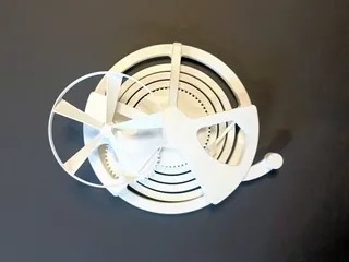
- Place the Upper Ring. Be aware that the 5 holes align with the bridgepart!
- Place the (spiral) Spring Ring. The spiral should turn left (outward to inward)!
- Apply a lubricant (I used Vaseline) to each axle end for the gears. You can also use a little lubricant for the spring.
- Place the Lower Ring.
- Secure the stacked parts with 5 M3x16 or M3x12 countersunk bolts.
Since this is a functional design, ensure that all protrusions / burrs are removed and that all moving surfaces are smooth. The axels should be a thight fit. Push the shaft ends into the provided holes and move them around for a while so that they wear into each other. Do not sand the shaft ends!
Store the spring in untensioned condition!
Instructions visualized (use the image I added to the photo section for bigger view):
Tags
Model origin
The author marked this model as their own original creation.