Wireless Corne Case
Top plate and case for Typeractive.xyz wireless Corne keyboard
118
804
6
7533
updated July 24, 2023
Description
PDFTyperactive.xyz Wireless Corne Case
This is a top plate/case that I designed to fit the Typeractive.xyz wireless Corne (https://typeractive.xyz/products/corne-partially-assembled-pcb). I really liked the look of curves on the Cornish Zen so I tried to replicate them in this design. It also has a little cover/extension for the on/off switch to make the case look a bit cleaner and provide some protection for it. The case uses the PCB bottom plate, standoffs, and screws from the Typeractive PCB case. I included a model of it in the files but I don't think 3d printed plastics are rigid enough for this application.
Build Guide
Print Settings
STLs are for the right half of the keyboard. Mirror the model for the left half
- Material: PLA+
- Layer Height: .1 mm
- Infill: 100%
- Nozzle: 0.4 mm
- Perimeters: 4
- No supports
Parts and Materials
- FR4 case from Typeractive
- https://typeractive.xyz/products/corne-case
- The bottom FR4 plate, screws, and standoffs are used.
- 1.75 mm filament for alignment pins
- CA glue
- Isopropyl alcohol
- Craft knife
- Sandpaper
- Jewelers files (optional)
Post-processing
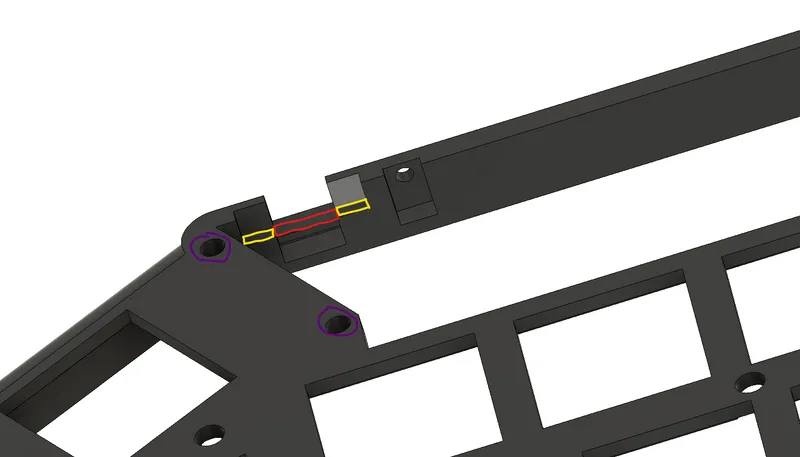
- Use a craft knife to remove the bridge material (red) and clean up the overhangs if necessary (yellow). Insert 2 sections of 1.75mm filament into the alignment holes (purple). Trim this filament so that appromimately 4mm protrudes from the top of the case. At this point you can do a dry fit with the display cover to make sure everything fits properly.
- Use a round jeweler's file or sandpaper to round out the holes for the USB C port on the Nice!nano.
- Lightly sand the bottom surface of the display cover to create a good mating surface for the CA glue. Only remove enough material to create a flat surface for the glue to bond to.
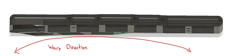
- The case will likely have a slight warp in it. This will cause the case to curl up slightly near the display and expose the bottom plate because there are no nearby screws to secure it. This can be mitigated by applying some downward force on the display cover during the glue-up. Have everything ready at this point since there is no going back.
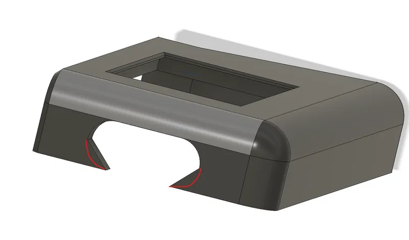
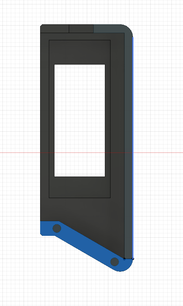
 Apply a thin layer of CA glue to the highlighted surfaces and the inside of the alignment holes on the display cover.
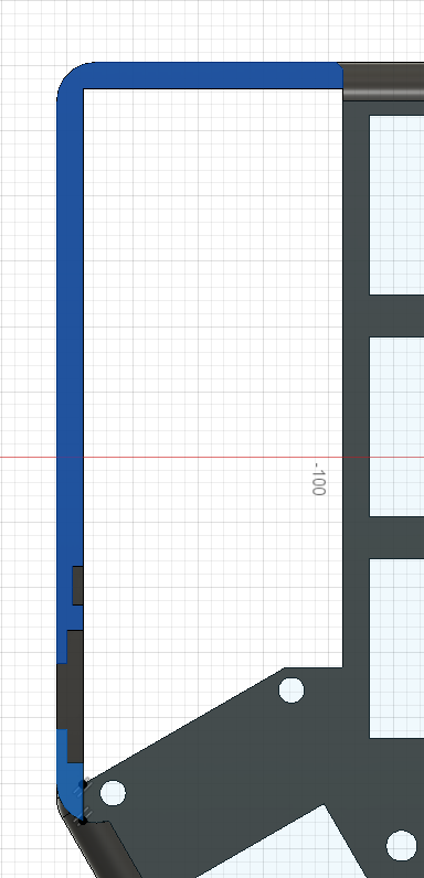
 Using the alignment pins, attach the display cover and to the case. Apply pressure to the display cover and bend the case in the opposite direction of the warping. Keep applying pressure until the CA glue sets. Most of the excess CA glue and be cleaned away with some isopropyl alcohol and some cotton swaps. Any remaining residue can be scraped away with a craft knife.
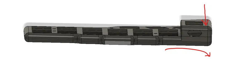
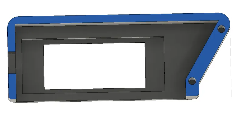
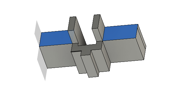
- Test the fit of the on/off switch cover. File down the highlighted surfaces if necessary. The switch should be able to slide in its slot.
Assembly
- Insert the switch extender into the case.
- Carefully angle the PCB with the Nice!nano and Nice!view into the case. Start by carefully aligning the of/off switch with the 3d printed extender. The on/off switch on the PCB is very delicate and prone to breaking, especially when removing the PCB from the case. Once everything is lined up, insert a few choc switches through the case and into the PCB to align everything and test the fit of the case. Check the alignment of the USB C port and the Nice!view. Test the on/off switch and reset switch.
- Attach the bottom PCB plate to the case using the standoffs and screws included with the plate case kit from Typeractive.
- Enjoy!
Tags
Model origin
The author marked this model as their own original creation.