Edge Lit LED Door Panels for Voron Trident

Description
PDFEDIT 02032023: I updated the HINGE BACKER. The Design of the hinge backer was creating interference with the vertical extrusion that was preventing the doors from fully closing. I also added hinges for doors using 3mm foam tape. I've also noticed the tolerance on the original hinges are too loose. I will be updating those files soon.
I have only tested this on the 300mm Trident with no foam tape on the panels. I will be making hinges that allow for 3mm foam tape. Also, these instructions are very vague right now. I will update them as time allows, but there are a lot of details you will need to work out for yourself, so if you are not comfortable with modding and figuring things out, DO NOT attempt this.
This mod uses laser etched cast acrylic door panels for LED edge lighting. In the US, cast acrylic is not readily available in 3mm thick panels. This design is for the standard 1/8" cast acrylic available in the US. You CANNOT etch and use the extruded acrylic door panels supplied with many kits. You can tell the difference by protective covering. If you peeled plastic off of your panels, they are extruded. If you peeled paper off your panels, they are cast acrylic and can be used.
The number of LED strips required per door, one or two, depends on the design you plan to use for your door panels. For simple, horizontal designs that are about 150mm or less in height, you can use a single LED strip at the bottom of the door. For more complex designs that are taller or vertically aligned text, LED strips at both the top and bottom of the door will be required.
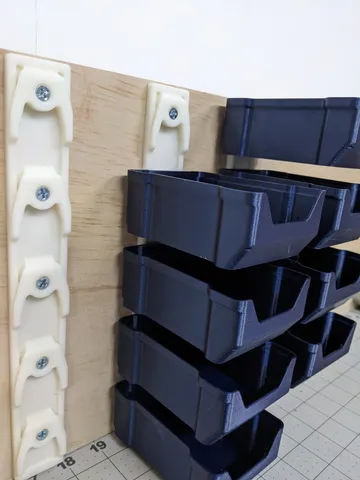
Printed parts required:
- Stealth slot covers - 2x 474mm long. You may need to get creative with this. On the 300mm Trident I was able to print a 374mm length and two 50mm lengths. This will place the seams at the hinges so the are not noticed. The stealth slot covers can be found here: Voron Mods - 20x20mm Profile Covers by chri.kai.in (vorondesign.com)
- 1x FRONT LEG, LEFT, EDGE LIT DOOR PANELS, TRIDENT
- 1x FRONT LEG, RIGHT, EDGE LIT DOOR PANELS, TRIDENT
- 2x HINGE, FRONT PLATE 1, EDGE LIT DOOR PANELS, TRIDENT
- 2x HINGE, FRONT PLATE 2, EDGE LIT DOOR PANELS, TRIDENT
- 4x HINGE, MOUNT, EDGE LIT DOOR PANELS, TRIDENT
- 4x HINGE, BACKER, EDGE LIT DOOR PANELS, TRIDENT
- If you plan to use bottom LED strips only:
1x XXX CARRIER 1, LED STRIP, EDGE LIT DOOR PANELS, TRIDENT
1x XXX CARRIER 2, LED STRIP, EDGE LIT DOOR PANELS, TRIDENT - If you plan to use top and Bottom LED strips
2x XXX CARRIER 1, LED STRIP, EDGE LIT DOOR PANELS, TRIDENT
2x XXX CARRIER 2, LED STRIP, EDGE LIT DOOR PANELS, TRIDENT
LEDs per strip required:
- 250mm Trident - 7 LEDs per strip
- 300mm Trident - 9 LEDs per strip
- 350mm Trident - 10 LEDs per strip
- The LED strip need to be the addressable RGB type with a 16.5mm or 16.6mm spacing (I measured mine and don't know the exact value). I used these strips from amazon.
Amazon.com: BTF-LIGHTING WS2812B RGB 5050SMD Individual Addressable 16.4FT 60Pixels/m 300Pixels Flexible Black PCB Full Color LED Pixel Strip Dream Color IP30 Non-Waterproof Making LED Screen LED Wall Only DC5V : Home & Kitchen
Hardware required for the hinges:
- 12x M3x8mm SHCS
- 8x M3 heat inserts
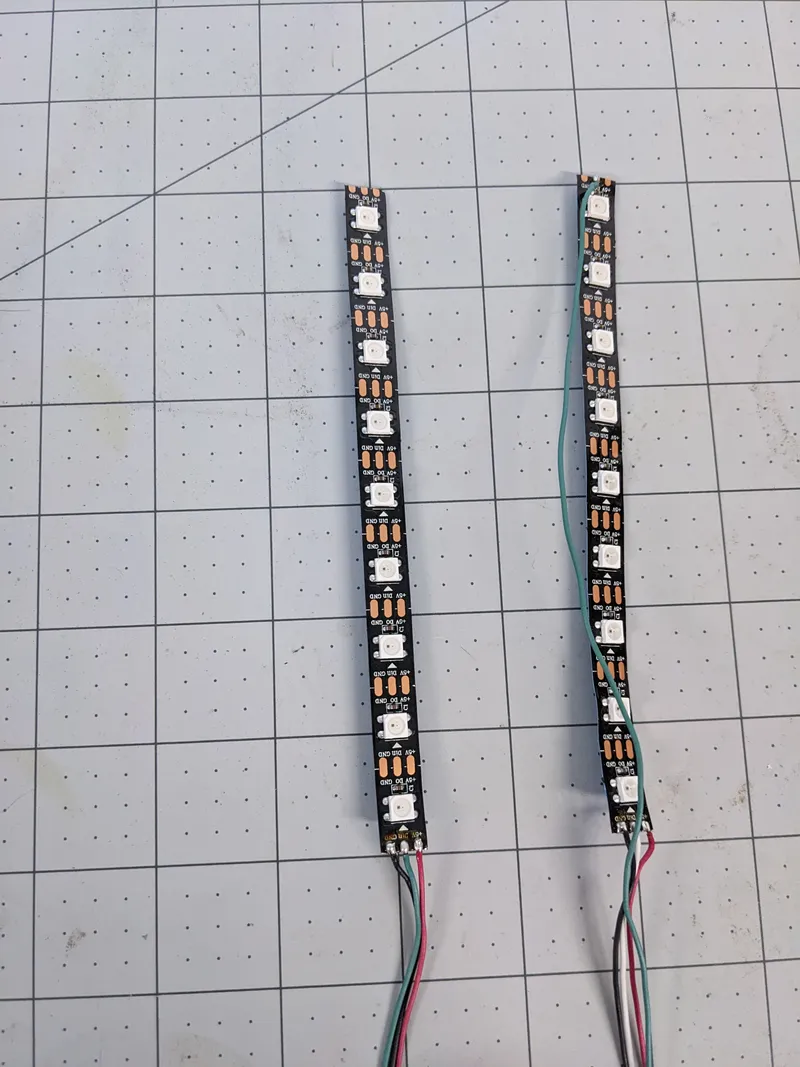
After printing the require parts, you will need to prepare your LED strips. I used 22awg wire that I had on hand. The strip that will be placed at the top of the door panel will require GROUND, POWER, and DATA wires on the IN end. The LED strip at the bottom of the door will require GROUND, POWER, and DATA wires on the IN end, and a single DATA wire on the OUT end.
In the image below, the top strip is on the left and the bottom strip on the right. It is helpful to use the same color wire for the bottom strip DATA OUT and the top strip DATA IN and a different color for the bottom strip DATA IN.
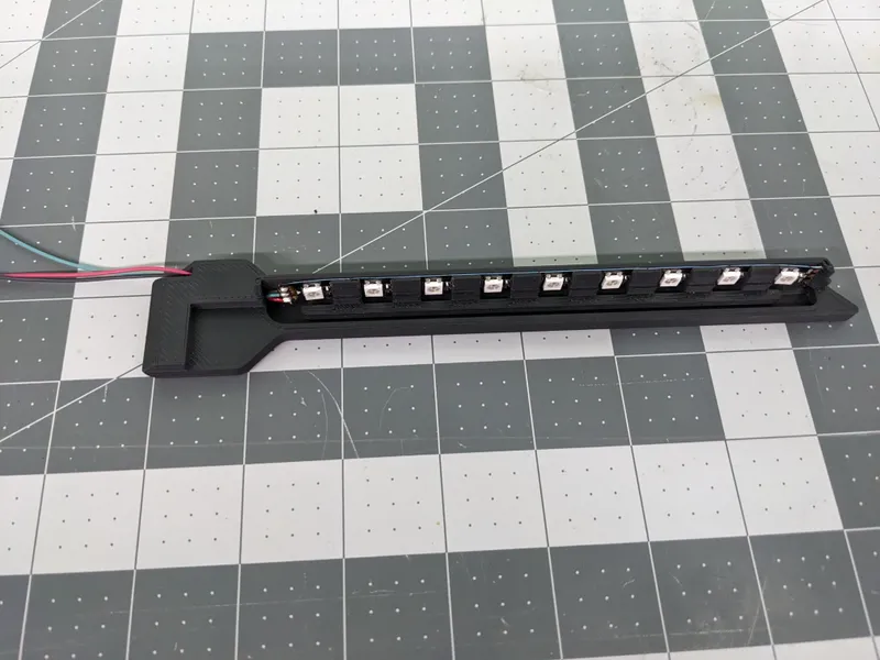
Next, feed the wires through the channel in the led carrier. Once the wires are pulled all the way through, you can slide the LED strip sideways into the carrier. Do not peel the protective film from the adhesive on the back. It is not needed and will only make it difficult to insert the strip. There is a channel above the LED strip in the carrier. This is for the DATA wire in the bottom LED carrier.
Top LED Strip
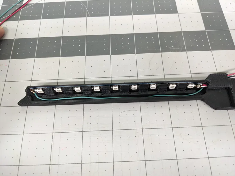
Bottom LED Strip
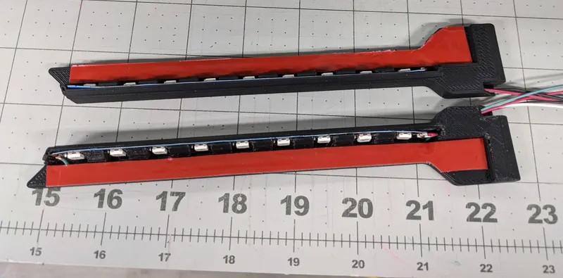
Apply VHB tape to the back of each of the LED carriers.
In the next steps you will be applying the LED strips to the door. Prior to doing this you will need to:
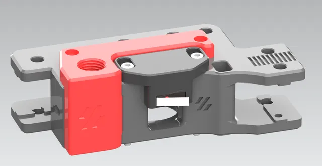
- Replace the front legs of your printer with the remixed legs in the print files.
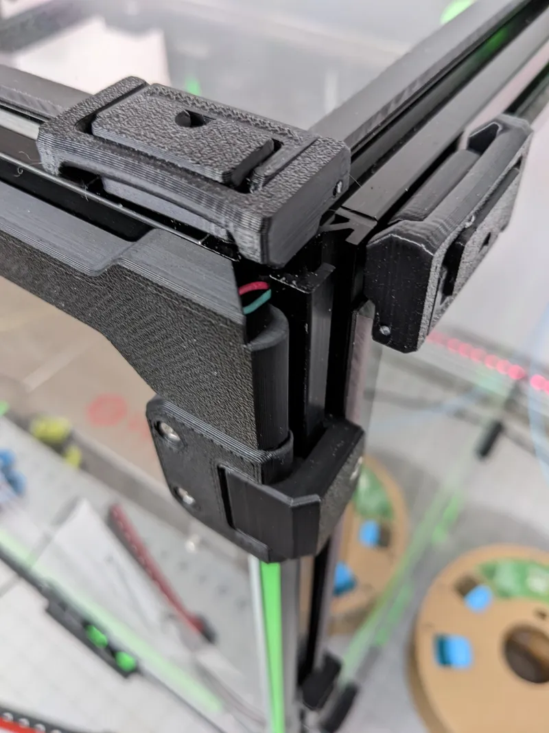
- If you plan to use both the top and bottom strips, you will need to insert the Stealth Slot Covers into the front of the vertical extrusions on each side of the door.
- If you plan to use both the top and bottom strips, you will need to replace hinges with the hinges in the print files. You can try other hinges, but they must be mounted on the sides of the front extrusions.
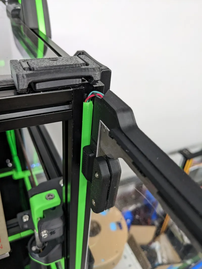
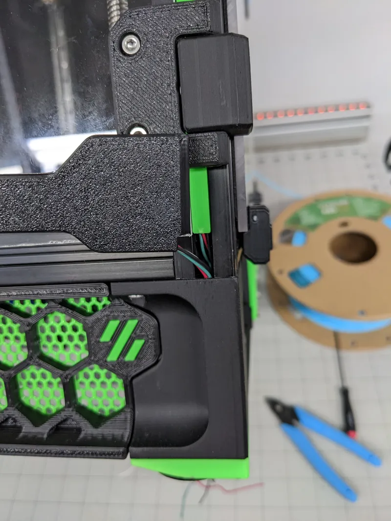
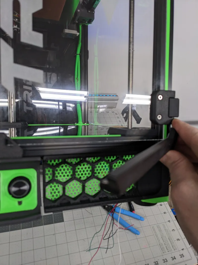
Feed the wires from the top LED carrier through the slot under the stealth slot cover.
Peel the VHB and with the door CLOSED, apply the LED carrier to the door panel so the LED strip is in the extrusion slot.
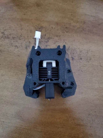
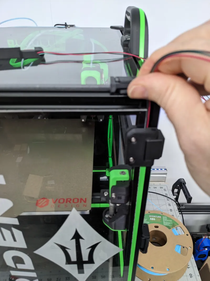
Next feed the wires from the top LED strip through the hole in the top of the remixed front leg of the printer. The wires though exit under the printer at the bottom of the motor.
The wires should appear like the image below.

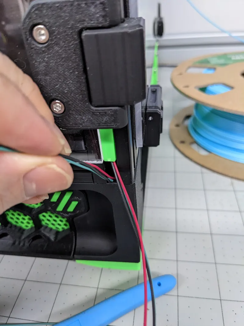
Now feed the wires from the bottom LED strip through the hole in the top of the LEG.
Peel the VHB and apply the LED carrier to the door panel.
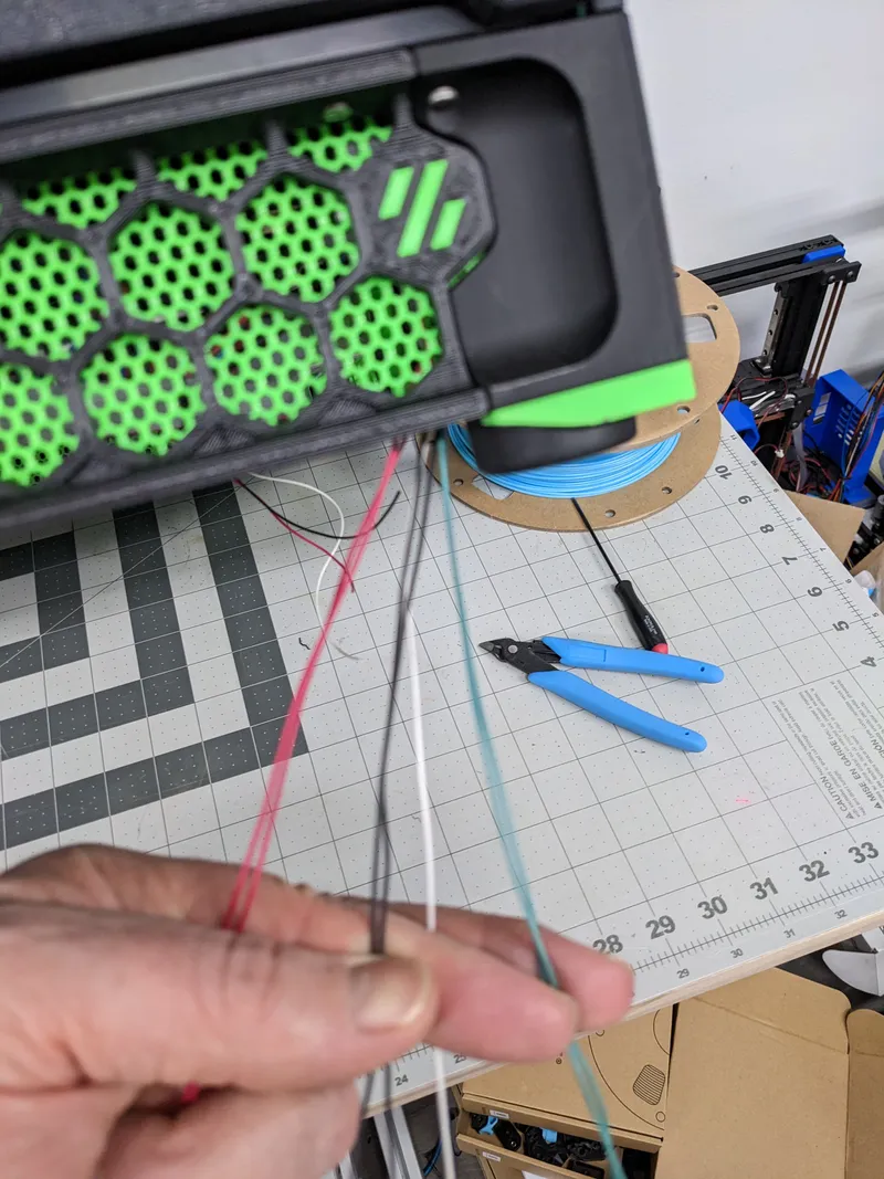
With the LED strips applied to the door it is time to sort out the wiring. The power and ground wires should be applied to the appropriate supply voltage and ground for the LED strips chosen. There should be 3 data wires left over. In this example, the white wire is the DATA IN for the bottom LED strip. This will be the wire that will go to the data pin on you neopixel controller or neopixel pin on your mainboard. The remaining wires are the bottom DATA OUT and top DATA IN. These wires can simply be joined together under the printer.
Tags
Model origin
The author marked this model as their own original creation.