Sovol SV06 SKR 3 EZ Mainboard Case Upgrade
Description
PDF…Please at least be sure to hit like & post a make, I'd love to see your prints!
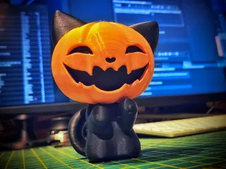
In conduction with 3DPrintDemon. Here's the all new mainboard case for the SV06 that is specifically designed for a SKR 3 EZ mainboard with 5 separate drivers! It easily slots onto the original mounting posts & locks in place with the original latch.
This means you will have separate Z motor control so you’ll be able to have a fully automatic printer controlled auto z align before every print using the probe & not running the extruder all the way to the top & grinding it out on the printer frame, the probe will get your gantry machine perfect before every print.
Also this means YOU DO NOT NEED ANY TINS OF SOUP!!
Fair warning, after you’ve printed it you’ll need to change some connector types over on the printer's main wiring loom & make your own long screen cable. Also you’ll need new Z motor cables. Or modify the ones there.
I strongly recommend using the correct tools & crimps for this, they don't cost so much on Amazon. See very last photos for the sort of crimp tools you'll need.
Use the 24v case fan out of the original unit.
This is super easy to print. It’s printed in two halves as an open box, then a group of small parts if you choose that option. The other version the cable port guides are printed in place, this will require more supports. The first version has separate cable ports & these are glued on after printing with good quality CA glue, like I have done here. It makes for a tidier print.
There's an open vent version without the demon face for those that want to either add their own cover or want to run without one for max airflow.
Printing
0.3mm layer height is good, 0.2mm is better
0.4mm nozzle is good, 0.6mm is better
Add supports inside all main case holes that need it, make sure your support settings are good & are easy to remove.
Add supports on the edge cutouts of the bottom & top cable port parts if you choose that version to print. No need to add supports to the two centre holes however. See note on the files section.
Print all cable ports & parts on their largest flat face, the one meant for gluing.
PLA+ is ok, PETG is better. With proper cooling the mainboard will stay below 30ºc when in use in a 22ºc room.
Make sure your printer is set up well, tolerances are tight & the fit is precise. A good clean print is very important, as a sloppy or messy print will mean things won’t fit & the unit will not work well & you’ll have issues mounting the board.
Parts
M3 Heat Inserts (5.7mm) - Recommend RUTHEX
Short (4mm) M3 Heat Inserts - IMPORTANT! - Recommend RUTHEX
2x M3 12mm Countersunk bolts - use on cover fixings
4x M3 16mm Countersunk bolts - IMPORTANT! Use on case fan! DO NOT USE OTHER TYPES! LOW CLEARANCE!!!
4x M3 6mm Cap Head bolts - use for board mounts
JST Connectors. The board comes with a bag of connectors but you will need a JST-XH crimp tool to modify motor cables - SEE PHOTO, tool with orange handle
JST plug pins can easily be removed from the connector & moved to another without crimps or any cutting or soldering. just use a pointed tool to push the back of the connector pin down & it’ll release from its housing. CAREFULLY bend the retaining pin back up & reuse in new connector.
2-4m 10 wire IDC 1.27mm Ribbon cable. You will need 1m per cable there are two cables.
4-8 10 pole IDC 2.54mm connectors. There are 2 per cable. Note, with these connectors they can be tricky to get right & even trickier to remove & reapply without breaking them. BUY MORE THAN YOU NEED!
Crimp Tool for IDC Connectors, you can get away with using mole grips or a small vice however. See last photos for the correct tool, red handled one. Also watch a YouTube video on how to crimp these.
Assembly
assemble all parts carefully, glue parts on the correct way round & DO NOT glue the cable ports together to form ovals, they need to be open & on separate sides of the case so they open.
Add the heat inserts & make sure the board fits perfectly. DO NOT force it or bend the SD card slot! That's a problem if you break it!
Attach the main case side to the printer. Add the fan to the lid & go by the boards pinout to make the correct connections. Making new cables & modifying the stock ones as you need.
connect the two screen cables to EXP1 & EXP2 ports this is different from the stock setup that uses only the EXP3 port.
VITALLY IMPORTANT!!! DO NOT MISS THIS!!
To set the board up for senseless homing on X & Y you need to add the smallest black jumpers from the supplied bag, DO NOT USE THE BIGGER ONES! See photo from the manual! I highly recommend you download & read the full document from the BTT Github page.
DO NOT add the jumpers to all drivers, just the first two - X & Y!
Also note the board PINOUT diagram on the BTT Github page!
DON'T FORGET TO BUY DRIVERS! Your board will come without any!
IMPORTANT!!
Also note stock SV06 screen has its EXP1 & EXP2 ports reversed, requiring one of each of the cable ends to be flipped. So if your screen doesn't work & stays dark you need to flip the connectors at one end of the cables & it'll work. I don’t mean swap plugs over I mean turn the same cable plug up the other way round & insert it upside-down, you can either shave off the plastic tab or replace & invert the cable in the connector so it’s the other way round.
See the very last photo of the cables!
The cable on the left is the normal cable you get with equipment & screens, this works on the stock screen in EXP3 for the stock board. This type of cable will also work for the BTT TFT35 screen in EXP1 & EXP2. BUT WILL NOT WORK on the stock screen in EXP1 & EXP2.
IMPORTANT!!
The cable on the right is the one I made that works on the stock screen using EXP1 & EXP2. You MUST duplicate this cable (x2) if you're to use the stock SV06 screen!
But these reversed cables WILL NOT work on the BTT TFT35 screen.
Tags
Model origin
The author marked this model as their own original creation.


