Bambu Lab P1P "Minimal" Enclosure

Description
PDFA minimalistic enclosure for the Bambu Lab P1P. It is designed to print with little material, fast, little to no supports and keep most of the original features of the case accessible with a possible upgrade path to existing models, that fit the bare printer without bulky stuff around. The bulk of the enclosure is covered with 3 mm sheet material (PMMA, PC, Wood, whatever floats your boat).
No bulky hinges, it uses the original X1 door and (optionally the X1 Glass Cover Plate) - or a replica of your choice in both cases).
Key Features:
- slim fit cover with no extras
- belt-tensioner is reachable without disassembly (like the X1)
- resource friendly (not much filament needed)
- pick solid side panels to your liking
- no heated inserts needed
- original Bambu and M3 screws only
- original Bambu Lab X1 door (optional)
- original Bambu Lab X1 Glass Cover Plate (optional)
BOM / What you need?
- just shy of 500 g of filament (you know where to get this)
- 12+ hours of print time
- 30 M3x4 screws (buy a set on Amazon; affiliate link)
- 0,33 to 0,5 m² of 3 mm sheet material (PC, PMMA etc.) rough sizes are:
- 2x 285 x 449 mm (sides)
- 1x 384 x 312 mm (top)
- 1x 320 x 355 mm (door, optional)
- some plastic glue (UHU Hart works for PLA, ABS and ASA; affiliate link)
- X1 door mounting kit + door (optional)
- X1 Glass Cover Plate (optional)
It is done, but read this before building!
The frame template from Bambu Lab quite differes from the real product, the cases seem to slightly differ from eachother, that is why there are so many weird shapes and cutouts, especially on the back.
This is needed to maintain the overall flush look and it the apparent 3 mm thickness of all features on all sides, even if they are thinner on the inside. unfortunately, if you use a translucent filament, those features would shine through.
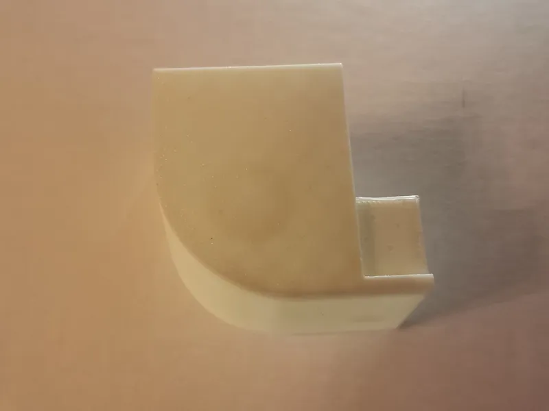
i recommend to print a test piece, a slice of the left rear top part (the actual corner) for example
Printing
it is designed to print on the P1P and the parts will fit there on one go, if you just need it quick an dirty - the “0.28mm Extra Draft”-Profile with infill reduced to 10 % works quite nice with Bambu PLA Basic - the surface is not pretty but it works like a charm - i still recommend printing it in a few batches.
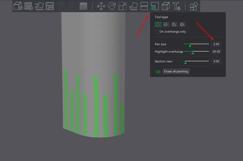
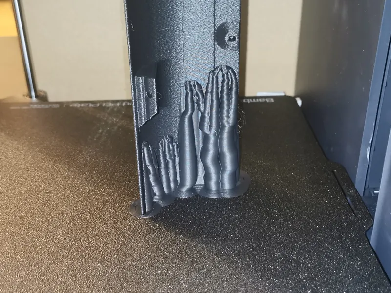
maybe add supports
with a more demanding filament or surface finish printing the thin upright parts are quite challenging and they might detach from the plate
if you have problems, just embedd everything in tree supports - they are easy to detach afterwards and leave no marks
Hide your seams
If you don't want an ugly seam down the front of your case, hide the seam on the inside of the shell
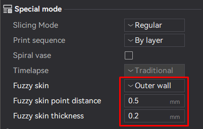
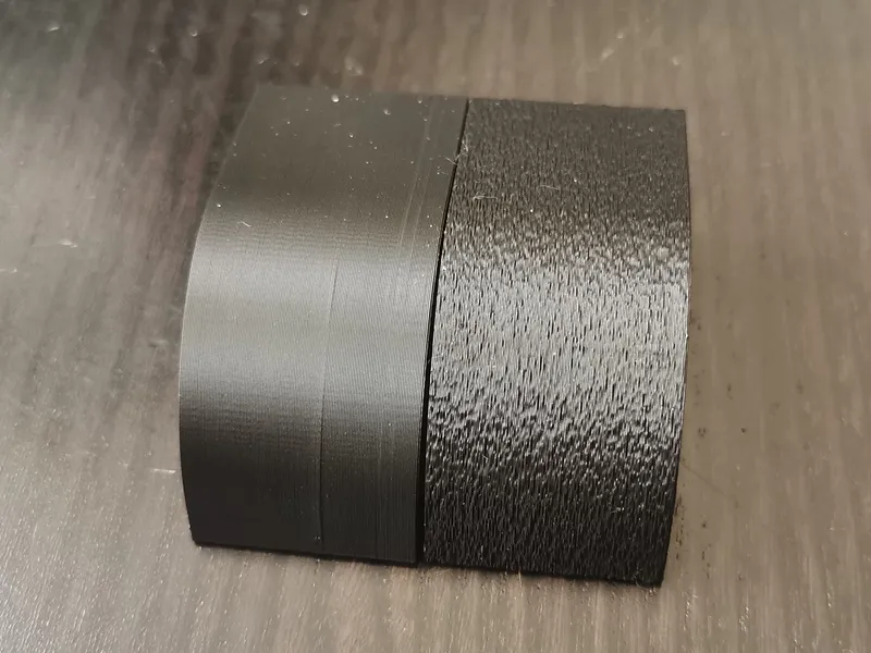
Fuzzy skin ftw!
Also if you don't like the minor layer shifts, you can work around this issue to apply a “Fuzzy skin” on the Outer wall. 0,2 mm fuzzy skin thickness is OK with the built in tolerance of the parts, everything fits pretty snug that way - a fair warning: this vastly increases print time and costs about 5 to 10 % more filament
Assembly
The enclosure is designed to repurpose the already built in screw + the screws delivered extra with the P1P for the official printable shells (those are not metric though, they are self threading and work in metal and polymers). You need to look at he mounting locations, some of them are threaded, some of them are not - use common sense for the screws
in short:
- Shell pieces use existing screws, M3x4 flathead or the additionally provided ones
- Panels use M3x6 countersunk (if you choose to countersink them)
assemble individual corner pieces
connect each matching top and bottom piece - they only fit one way
since there is a built in tolerance to hide the seam in the front you'll have a pretty tight fit on the outside but a little gap at the back side - this is totally normal, don't force the hidden back side together, else you'll get a crooked part
permanently join the pieces (optional)
depending on the surface finish and material, the pieces are designed to friction fit
i still recommend gluing the matching top and bottom pieces together, it is easier to handle this way
however, i do not recommend gluing the back left/right panels together, since they are assembled with screws from the left and right side and are a bit fiddly to move in place
mount the front pieces
the front pieces are straight forward, each module uses 5 screws
start with the left panel to get comfortable with the mounting positions, don't forget the upper screw hole, be careful not to damage the cable
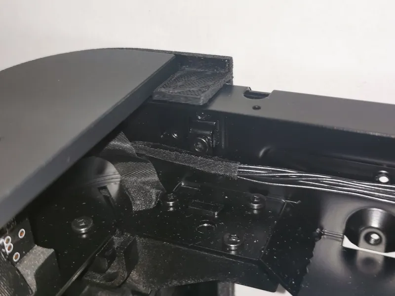
since the right side is recessed, it has a lip which block the scew holes partially,
you can fasten them like shown in the picture
remove the rear panel
follow the instructions to remove the remove the rear panel first - unplug your printer! you'll be working right next to the MC board and bower board (you don't want to electrocute yourself)
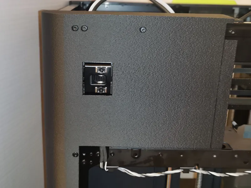
mount the right back piece
viewed from the back: remove the upper 2 screws at the top left side where the backpanel will be, also the 2 screws left of the rear panel
place the shell and secure the panel at the following locations
- 2 screws from the inside of the removed rear panel
- 1 screw from the inside of the printer
- then replace the 4 screws you removed earlier + 1 extra from the outside in the center
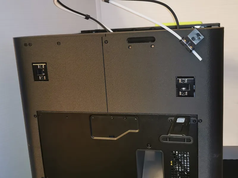
make sure, the cable for the stepper motor is funneled straight down in the cutout channel like shown in the picture, else it will get pinched and the shell bulges out a bit
mount the left back piece
same procedure as before: remove existing screws: the 2 “weird” screws from the bowden connector, the screw in the center and the 2 next to the back panel
place the shell and secure the panel at the same locations as on the right side
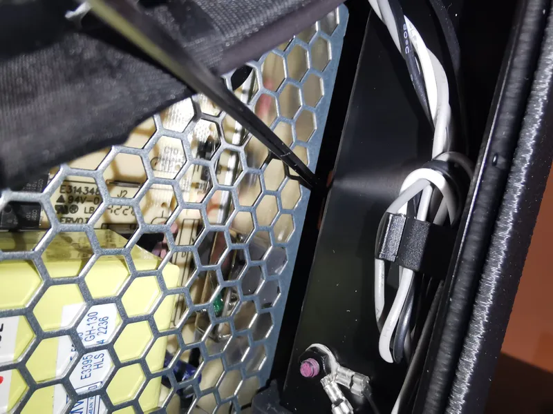
tricky pat is, you to mount 2 screws right next to the power and the MC board - you can reach both locations with the original Hex 2.0 allen key, but make sure the hole aligns properly
avoid losing the screw, it is a pain to get it out - either use a magnetized screwdriver or use a toothpick and apply a tiny spec of gluestick in the screw head to make the screw stick
the upper location is found right here
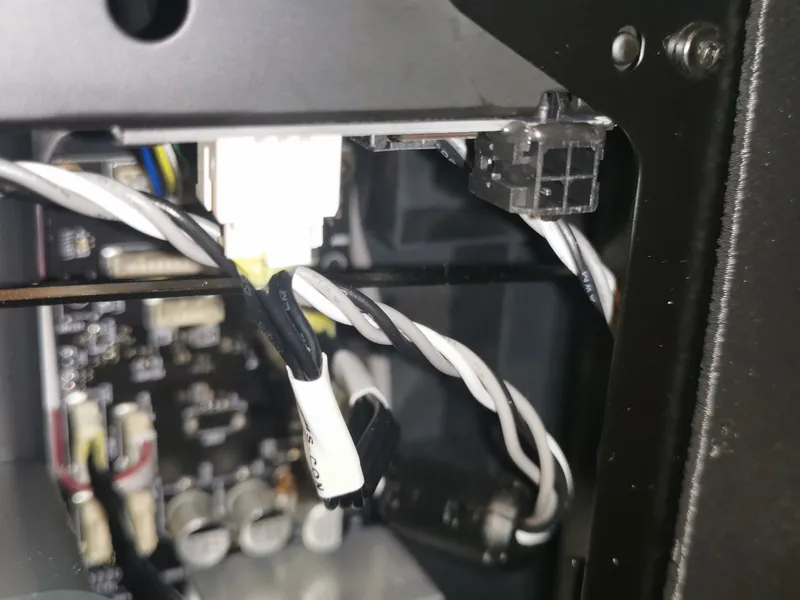
the lower location here
mount the rear panel again
screw back the rear panel, refer to the original article where to place back the screws, it should look like this now
mount the panels
measure and cut the panels to size with the real dimensions after mounting the shell - they might differ a small amount
5 screws each for left and right panels - countersunk prefereably
the top is just gravity fit - you can glue a EPDM-foam strip on the frame, to dampen the vibration
mounting the door
(WIP - needs bit of time, to provide the files and document the process)
front plastic cover
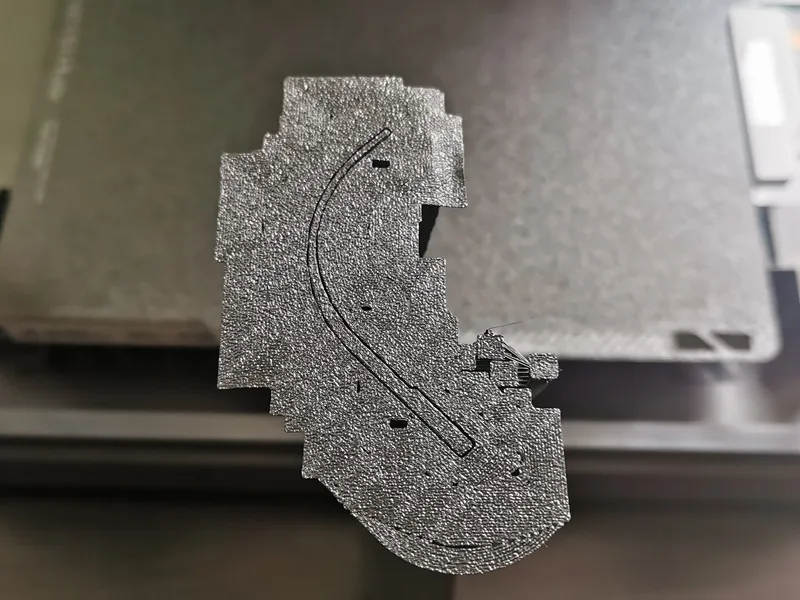
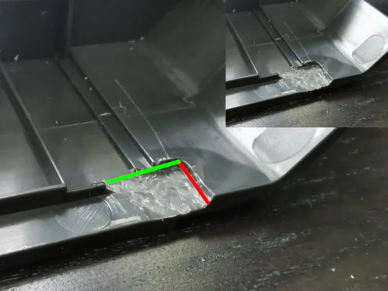
remove front plastic cover according to the official instructions. once the piece is separated, you need to modify the piece and make a cutout to make room for the hinge. The red line is about 6 mm long, the green line is about 9 mm long (4,5 mm in both directions from the ridge), you need about 2 mm of extra space - there is plenty of material to keep the part stable and it won't be seen from the outside afterwars (but still: work carefully)
after the, mount the DOOR_FRAME piece onto the plastic cover
the piece is simply mounted with thin double sided tape to the back of the part, it is enought that it does not fall off and is later wedged left/right into the frame and does not fall out - the tape is just that it does not vibrate
rubber gasket
cut off the right and top rubber lip (~ 1 mm of the right side) of the gray gasket with straight edge and a very sharp blade and stick it to the frame according to the assembly instructions
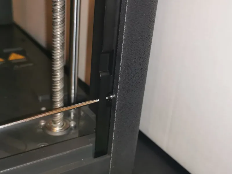
hinges
mount the hinge mounting kit - but be aware, that you don't need to bend the lower left frame - you can just unscrew the front left colum (4 screws from the front/left and one from the bottom), then you move the piece out of the place to screw down the hinge and then put the screws back
if you use your own sheet material you can either paint the edges to hide the hinges or use the HINGE_COVER pieces to cover those up - on the original X1 door you don't need this
reinstall the plastic cover
congratulations, you are done
Door and Top Handles
you can use the original Door Knob / Handle or another one of the many found on here on printables.
Post a make & give me feedback
Now that you've sucessfully assembled the enclosure, snap a picture and post a make.
Drop me some feedback, maybe there is room for improvement!
Troubleshooting & FAQ
The upper back parts don't fit and have a gap!
they are 100 % dimensionally accurate in the design
depending on various factors, your print might not be 100 % dimensionally accurate - the back side of the shell measures rougly 390 mm if it contracts by only 0,1 % you'll have a gap of almost 0,5 mm between the pieces, enough to let light shine through - also the metal frame of the printer expands with the temperature - if you start with 15°C in your cold workshop and heat it up to 55°C after a long print job, it expands about 0,25 mm.
If this shrinking and expanding gap triggers your inner monk: you'll get EVA craft foam in various colors and thicknesses, just cut a small slice of a matching color and use it as a flexible gasket - or use a string of TPU filament
The DOOR_FRAME piece is too short
since this piece is very long and narrow and is printed in a 45° orientation, you get very long strands of extruded filament that contract during cooling and make the piece shrink a bit (depends on the filament, some shrink more than other)
there are 2 ways to work around this issue: first change the orientation for top/bottom layers and infill direction - it defaults to monotonic/monotonic lineand is orentied 45° to the x/y axis - so when you rotate your piece by 45° those patteres are parallel the lenght axis of the piece, which makes shrinking in this direction worse - just change the the value for Strenght → Advanced → Infill direction” from to 45° 0° - this with also change the direction of the top/bottom surface pattern
if this is still not enough, measure your piece after printing, and scale it up to compensate for the shrinkage
Is the the Enclosure compatible with the original top glass cover of the X1?
Not without modifications, that compromise the clean look, this has 2 main reasons:
- The front plastic frame of the P1P is about 6 mm deeper than the X1 frame, so it would not be flush on the back and would overhang or need to sit on top of the plastic frame (which is both not ideal imho)
- It is intended to be easy and cheap, the design therefore uses a rectangular piece of sheet material, it can be easily cut by everybody with a circular saw or bought online precut - no roundover needed.
If you still want to live with those drawbacks, there is an alternative set of rear parts included - all other parts stay the same
Changelog
next up:
- customized knobs for the top cover and the door
- a few more “decorative” trim and spacer pieces
- as soon as the P1S back panel is available: modified back panes (will become a separate project, ETA February 2024)
v48 (2023-04-17):
- added DXF files for the side and top panels - beware, left and right side are not the same, since the center mounting locations are on a different height for both sides - also the hole distance for front/back is not the same - so make sure to mount them in the right orientation - no need for drilling extra holes
v47 (2023-04-15):
- added a template for the door. keep in mind, that the measurements are provided from a 3rd party (thx to Morgen Kaffe for the measurements)
i used those to create my own door but it is not yet tested by others. if you make one yourself, i'd appreciate some feedback
v46 (2023-03-19):
- new additional piece HINGE_COVER - a small plate to cover up the door hinges, if you don't use the original door
- new additional piece BEAM_TRIM - covers the left and right beams and act as a spacer - looks nicer, when you use a transparent material
v45 (2023-03-06):
- all parts fully compatible with the previous version
- plastic frame spacer (DOOR_FRAME) to fill the gap for the door
v41 (2023-02-16):
- fully compatible parts
- changed the rear upper parts to provide a bigger lip to rest the to plate on
- BETA files for the original top Glass Cover Plate (those are not fully tested)
v39 (2023-02-02):
- QOL: reuploaded all files, print orientation of some pieces was upside down
v38 (2023-02-01):
- fully compatible parts again
- minor changes both upper back parts
- yet more cutouts / fillets to make space for screwheads
v37 (2023-01-29):
- parts are fully compatible to previous versions
- front right (both pieces) got a lip on the inside to make it look nicer
- front left (top and bottom) got a bit more clearance to the fold
- back panel cutouts with fillets to make them less visible on translucent filaments
v34 (2023-01-28):
- public “stable” release (no changes from this part on that will break compatibility with the older pieces)
- redesigned rear top parts
v30 (2023-01-27):
- size and tweaking to front/back pieces for a tighter fit with more room for error
This is the same as “Enclosure …”
I was not satisfied with the cases provided by Bambu Lab and also the work from others at the did not 100 % fit my needs. So i designed my own.
During the process i stumbled upon the Vision Enclosure. It is a solid design, it came close to my wish list, i tested it and helped iron out some issues, but after all i did not like a few things (sidepanels are not fixed, hinges …) - so i came back to my design which was already almost completed at this stage.
After all most of the cases here are “just” some corner pieces with some sides and a top slapped on. The difference is usually in the details, especially the back panel, how the top panel attaches and the hinges for the door mechanism. Compare them and decide which one fits your needs.
As said before: i don't like visible “stuff” sticking out over the general shape of the enclosure (like handles, hinges etc.) - but this is my taste.
If you want something fancy and bulky, check out the Companion Cube P1P Mod
Tags
Model origin
The author marked this model as their own original creation.


