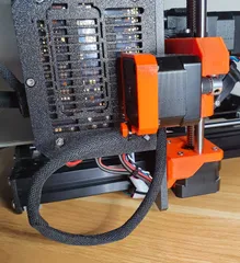
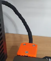
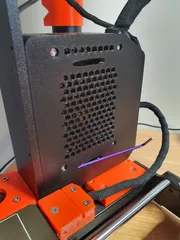
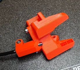
MK3 rear-mounted nozzle endoscope camera holder with anti-rotation lock
Description
PDFUpdate 18 Nov 2023
I recommend no longer using this rear camera arrangement.
After some use I was a bit heavy-handed with the locking screw and damaged an endoscope camera. I would not like that to happen again.
Also, I have always found the rear view to be not visually ideal.
The release of the Delta-P cooling duct has allowed the easy use of a front-mounted camera.
See my posting of a that camera system.
https://www.printables.com/model/646810-mk3s-endoscope-nozzle-camera-system-for-the-delta-
Background
A working nozzle camera was an imperative for me as I am legally blind and need a big screen view of what’s happening at the hot-end.
Endoscope types
I have experimented with a range of endoscope sizes. What I found was the best image quality is with the larger diameter endoscope. However, as endoscope are not made specifically for this application, larger endoscopes tend to have auto-focus which play constant catch-up as the extruder moves, making those types useless for this application. Another trend I found with larger diameter endoscopes was an increase in the focal length as the makers try to achieve infinity focus. This also excludes these types from this application as they have poor focus at the nozzle, producing poor image quality.
Another factor is the limited availability of endoscopes with a soft, flexible cable.
The majority of endoscopes on Amazon seem to be the rigid cable types which are not suitable for securing into the MK3 extruder loom. I found the widest range of useful options on Aliexpress.
With close, fixed focus being a requirement, it came down to a choice between the cheaper 5.5mm diameter which has been around the longest, and the more expensive 3.9mm diameter which is claimed to have “better technology”. But image quality is not just about the image resolution set by the electronics. The clarity of the optics plays a part as well.
Testing bot the 5.5 and 3.9mm types, I was surprised to find how toasty hot the 3.9mm was, close to the tip. That is a longer term concern given the aggressive environment close to the hot-end. While printing, I measured an ambient of 60°C near the tip of the endoscope. (Hot electronics?)
Comparing both the 3.9mm and 5.5mm, I found the 3.9mm has a noticeably clearer image. But that may be an adjustment issue.
My camera setup plugs into a Raspberry Pi4B with Octoprint streaming to my PC with a 42.5” display which helps with my vision issue. But many camera viewing arrangements can work too.
Design Goals
The design aim was an MK3 extruder rear-mounted endoscope that:-
1. does not interfere with operation of the MK3, including during calibration,
2. uses the existing M3*40mm cable loom mounting screw,
3. is able to be fitted with no more disassembly of the extruder or loom than removing the cable loom screw and cutting the cable ties.
4. is able to be printed without support using default slicer settings.
Features
During calibration, the MK3 extruder moves to both the left and right extremities, sensing when the limits are reached. It is important not to interfere with that movement.
The holder has a notch on both side, indicating where the MK3 frame will come close when calibrating.
The hot-end cables are relocated from underneath to the left side. Close attention is needed to locate the sensing and heater cables shown to avoid a situation where the cables bulge out the left side, interfering with the calibration process.
An M3 grub screw is provided to lock the endoscope position and rotation.
An angled bed face is provided to allow printing without support.
Parts required
1 * endoscope camera holder print – 3.9mm or 5.5mm
1 * endoscope camera – 3.9mm or 5.5mm
1 * M3 x 40mm screw (Use existing screw)
1 * M3 x 6mm cup grub screw
1 * M3 thin nut DIN562 (Use one from the Prusa MK3 spares bag)
3 * 2.5 x 100mm Cable Ties
2 * 2.5 x 150mm Cable Ties
I sourced the cameras from Aliexpress:-
a) 5.5mm camera, 1 metre - soft cable
b) 3.9mm camera, 1 metre - soft cable
I used cable ties from a multi-colour kit for easy identification but all black is good too.
Assembly
I found the cable ties more easily fitted prior to fixing the holder to the extruder.
The loom is held by three 2.5 x 100mm cable ties, the blue ones as seen in the photos.
The 2.5 x 150mm cable ties for the hot-end cables have a slightly longer internal path, going under but not touching the endoscope, the yellow ones as seen in the photos.
The holder design assumes the sensing cables are placed behind the heater cables. Close attention should be paid to this as arranging the cable in another way can lead to excessive bulging of the cables out to the left, potentially interfering with the MK3 calibration process. The photos show excessive bulging which should be corrected by placing the sensor cables underneath the heater cables.
Some variability might be found in your MK3 hot-end cables. In my MK3, I found excessive length of the heat-shrink, making the cable bundle fatter that needed. I carefully trimmed back the heat-shrink to a more reasonable length. Careful inspection of this is needed prior to placing the hot-end cables into the cavity of the printed part.
Hot-end cable assembly check
Before final securing of the cable ties, move the partially assembled extruder fully to both the left and right to ensure the extruder moves freely all the way to its maximums.
Once it has been proven that the MK3 calibration can be executed properly, pull all the cable ties tight and snip off the excesses.
Image quality.
Good lighting can assist with image quality. The endoscopes have adjustable inbuilt LED lighting enough to illuminate the nozzle. However, the source position of the LED lights is not ideal. Light reflecting back into the camera lens from the heat-block can wash out the image on anything but low intensity light. But I have found that setting the LED light on low intensity with good ambient lighting is sufficient for acceptable images. But it is an area that could be improved as others have done on other 3D printers, but not so far on the MK3.
Image Adjustment
As a guide for both the 5.5mm and 3.9mm endoscopes, good focus on the nozzle should be found with the tip of the endoscope protruding about 8mm out of the holder.
Adjust the position and rotation of the endoscope for a horizontally correct image with good focus. When satisfied with the image, gently turn the grub screw to lock the endoscope in place. Be careful not to over-tighten the grub screw as this might damage the endoscope.
Final Assembly
Once the image adjustment is complete, the soft, flexible endoscope cable can be zip tied to the extruder loom.
29/01/2023
Upload of additional photos showing the method of tightly packing the hot-end cables.
These photos were taken of the 3.9mm endoscope, set to it's focus position.
4/05/2023
Update - 3 months usage.
After 3 months usage of the 3.9mm camera, mainly with PETG, I found the image was becoming increasingly foggy. I thought the camera lens might be degrading due to the high ambient temperature.
So I removed the camera and in the process touched the lens. The image had become clear again.
I must assume the camera lens had collected a film from the hot gasses during printing.
If this happens to you, a simple wipe of the lens with a soft cloth should restore the image.
During removal of the camera I found it had become very tight in the printed part.
I intend to open up the throat a little in a new version.
Until then I recommend running a pin file file in the throat of the printed part to ensure the camera can be removed easily.
Model origin
The author marked this model as their own original creation.


