Clickable Touch ID Box (TKL board, wired)
Description
PDFThis model is also editable on Tinkercad
This model is only for the TKL keyboard (the one without a number pad), if you have one with the number pad, the circuit board will not fit into this box.
!!! C plate must be printed with 0.1mm layer height !!!
Differences from SnazzyLabs's model
- Centered Touch ID button (SnazzyLabs's wired TKL model has the button off centered by a few millimeters)
- Clickable
- No glue
- No supports
- No screw brass inserts
- No drilling the board
Material
- 1x Magic Keyboard with Touch ID
- 11x M1.2x4 screws (2 for the lightning port, 2 for the board, 7 for the button)
- 2x M1.2 nuts (for the lightning port)
- 4x Rubber feet (optional)
- Electrical tape (optional)
I bought these on amazon (non affiliate links):
140pcs Hex Nuts M1/M1.2/M1.4/M1.6/M2/M2.5/M3 Stainless Steel Hexagonal Nuts Thread Fastener
Instructions
- Disassemble a TKL Touch ID Magic Keyboard. See this guide and this video. (I used a heat gun instead of iOpener) (@Seth_10131 suggested heating the back of the keyboard with the print bed)
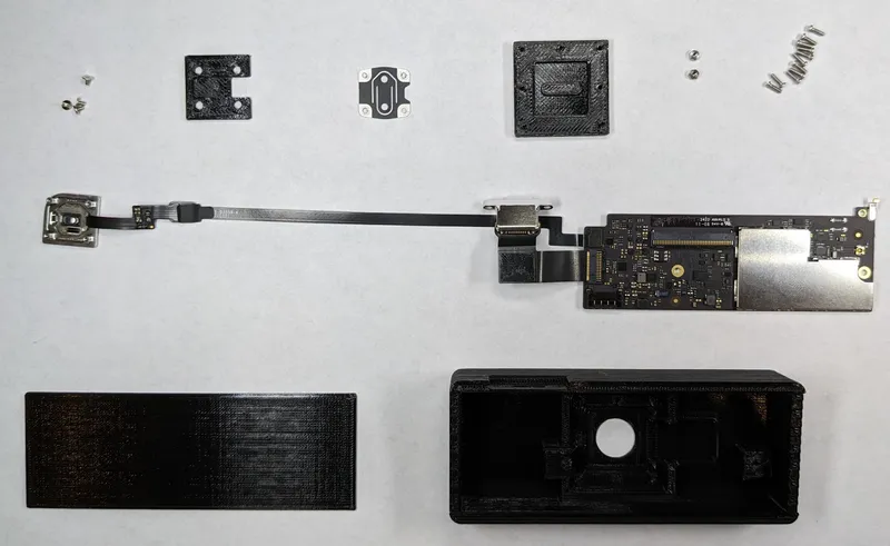
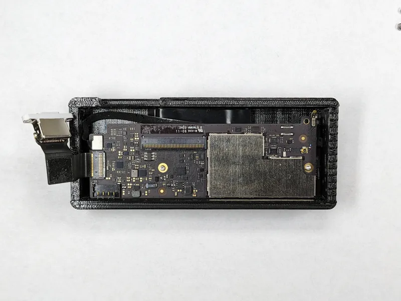
You'll need these parts from the keyboard:
- Circuit board
- Lightning port
- Touch ID button + ribbon cable. You'll need to remove the key cap on top of the touch id button (like in this clip). The button should look like this after the key cap is removed: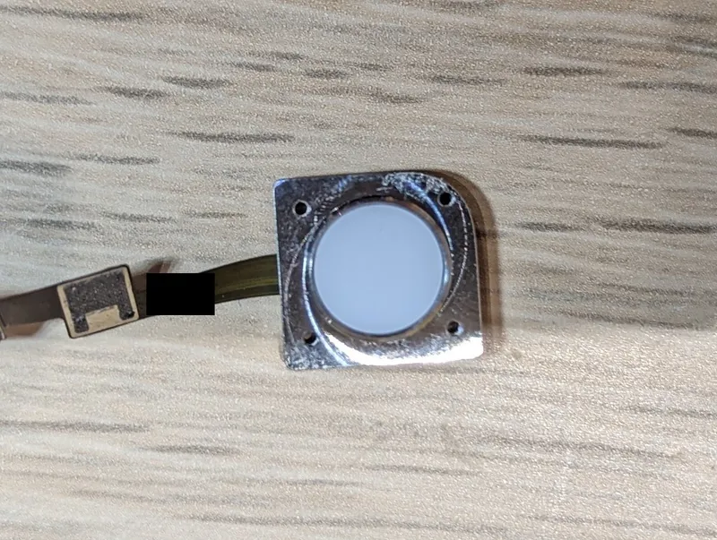
- Spring plate
- These 4 screws that attach the spring to the button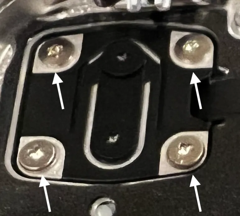
- Print all 4 parts, the C plate must be printed with 0.1mm layer height. Everything else can be printed with 0.2mm layer height. The C plate details can come out slightly differently on different printers, put the button into the C plate to test the click before assembly. Sand down the top if it doesn't click. (See more in Notes)
- Put button in the center
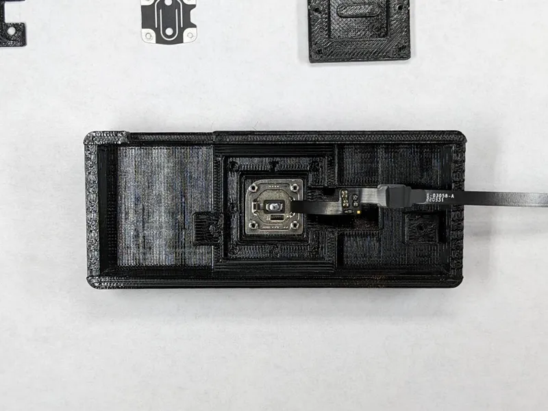
- Put C plate on top of button
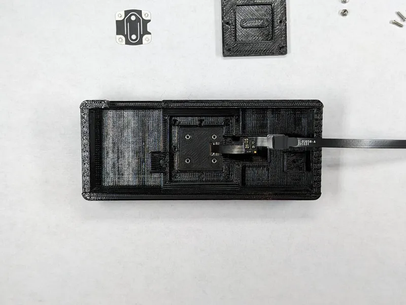
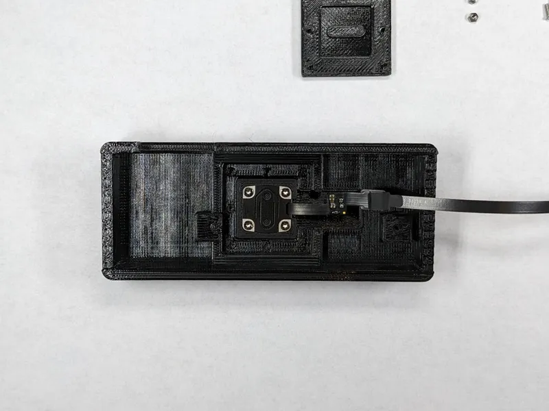
- Test to see if the button clicks, file down the raised center point on the C plate if needed. Screw on the spring plate. Note the orientation in the photo below.
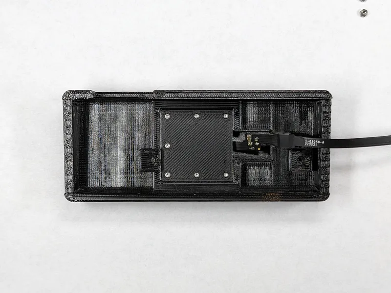
- Screw on the back plate. The side without a screw hole should face the ribbon cable. (7x M1.2x4 screws)
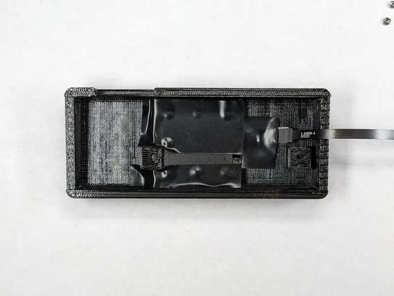
- (Optional) Put electrical tape on all metal bits that could come into contact with the circuit board to protect it in the very unlikely event of the screws falling out.
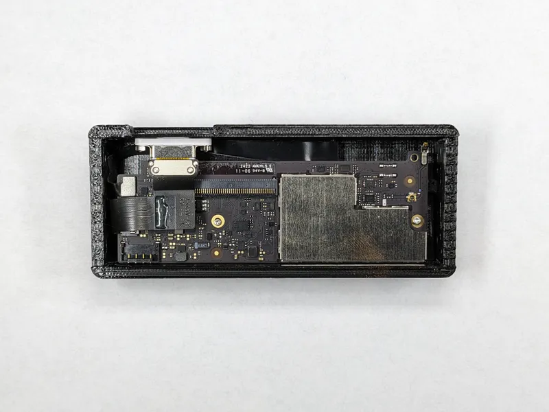
- Screw on the circuit board (2x M1.2x4 screws)
- Screw on the lighting port (2x M1.2x4 screws, 2x M1.2 nuts). This step can be tricky, using a pair of tweezers to hold the nuts or switching to longer screws could help.
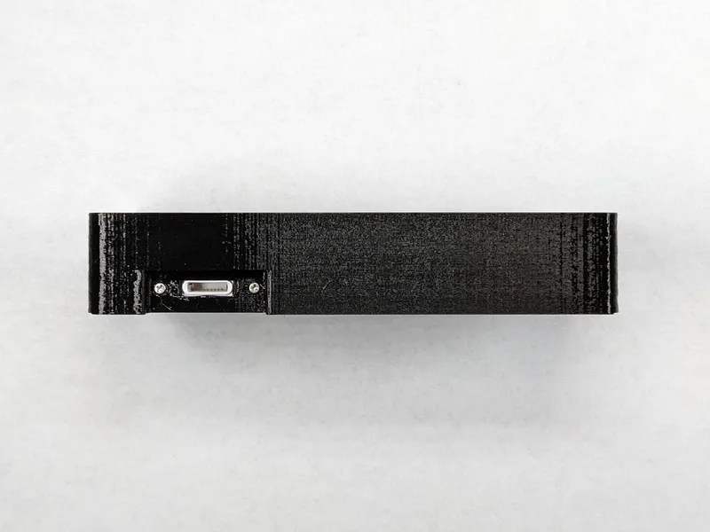
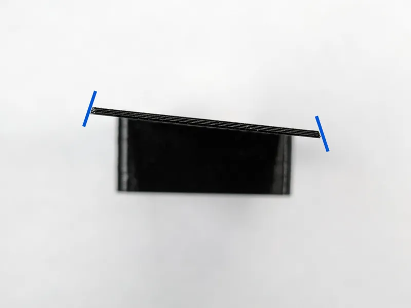
- Slide the lid on to the box. The long sides of the lid is angled. The wider side should face the circuit board.
- (Optional) Stick rubber feet on to the lid
Notes
I printed the box and the lid with my Prusa i3 MK3S+ with MMU2S on my Double-sided Powder-coated PEI Satin Spring Steel Sheet, with Prusament Jet Black PETG with no support and with 100% infill. The box, lid, and back plate are printed at 0.20mm QUALITY settings. The C plate is printed at 0.10mm DETAIL settings. The box and lid are printed at 90° fill angle (to looks prettier). The C plate and back plate are printed at 45° fill angle. The top surface of the box and the back plate are lightly sanded with 320 grit sandpaper.
Credit
Main Design from SnazzyLabs's model
Clickiness inspired by GLOUPY's model
Tags
Model origin
The author remixed this model.

Differences of the remix compared to the original
- Centered Touch ID button (SnazzyLabs's wired TKL model has the button off centered by a few millimeters)
- Clickable
- No glue
- No supports
- No screw brass inserts
- No drilling the board