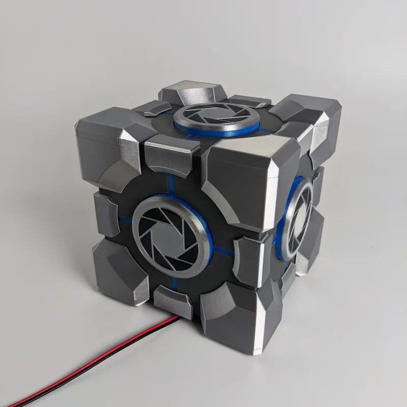
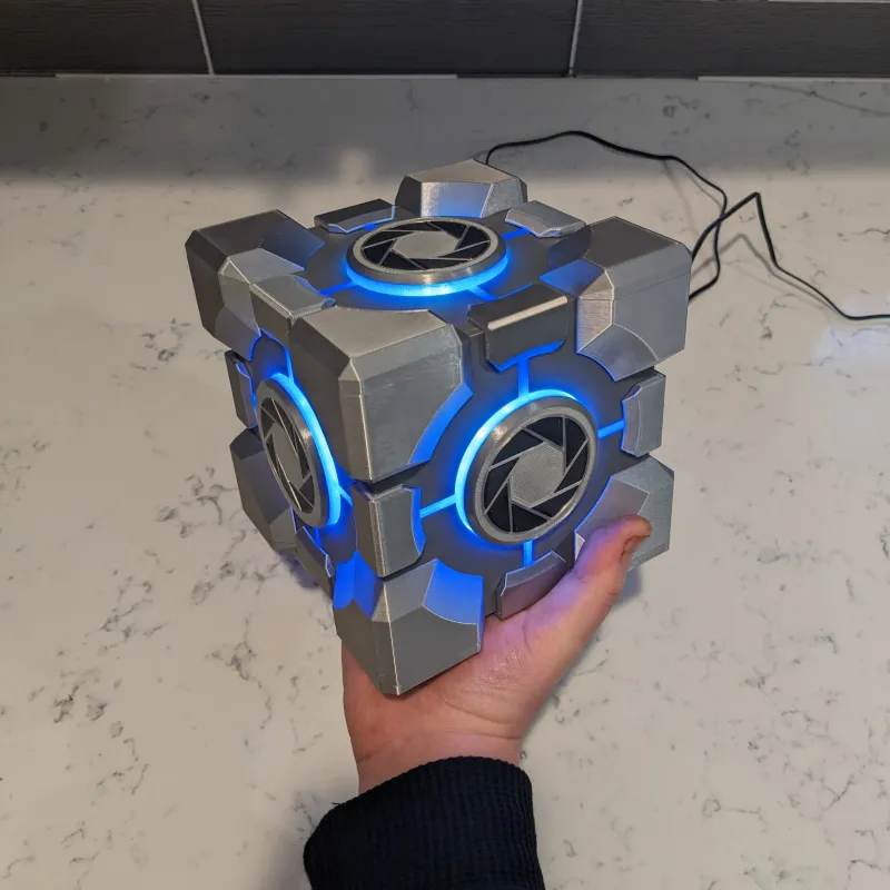
Portal with RTX Weighted Storage Cube
This is my take on the Weighted Storage Cube from Portal with RTX
205
182
1
3872
updated December 13, 2022
Description
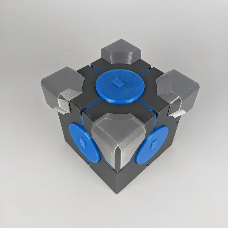
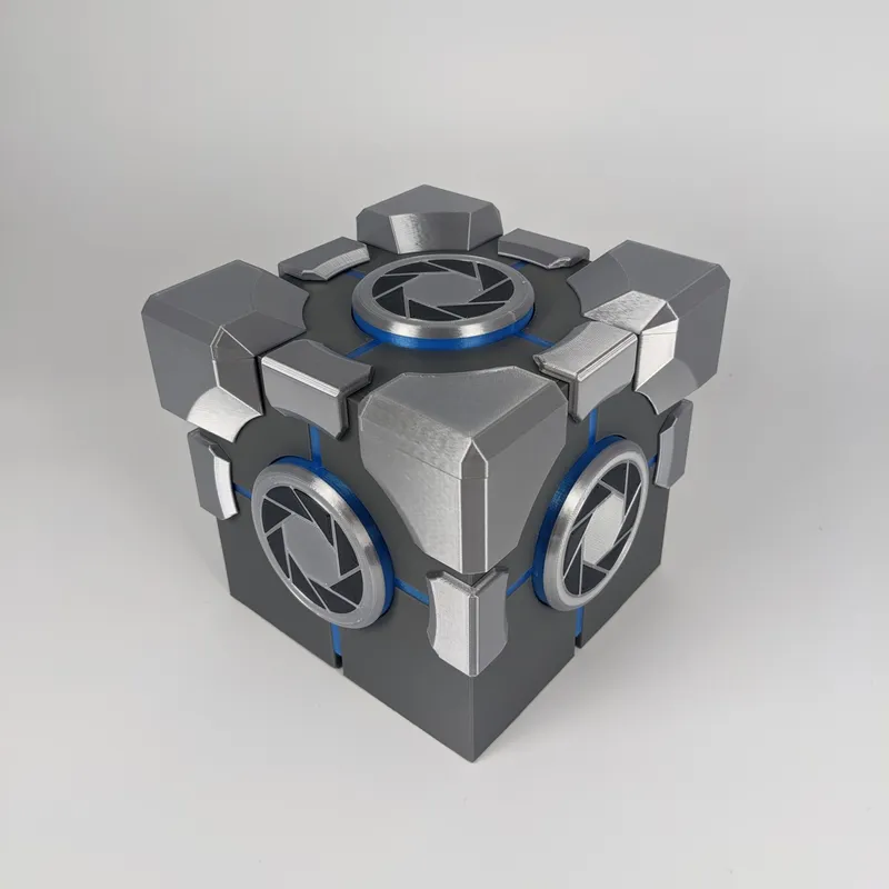
PDFThis is my take on the Weighted Storage Cube from Portal with RTX. It's 150mm x 150mm x 150mm or 5.9" x 5.9" x 5.9" in freedom units. There are a few things that can be improved like consolidating the inserts that make up the Aperture Science logo into one piece which I may do in the future.
Tools needed:
- Soldering iron + solder + shrink tube
- Hot glue gun
- Scissors or cutters
- Hookup wire
List of consumables for this build:
- PLA
- Jayo PLA Grey: https://www.amazon.com/gp/product/B08CZKNY3Y
- Hatchbox PLA Transparent Blue: https://www.amazon.com/gp/product/B00M0CS4YA
- Geektech Silk PLA Metallic Silver: https://www.amazon.com/gp/product/B07QGV6D8P
- 40mm Fan: Noiseblocker NB-BlackSilentFan https://www.amazon.com/gp/product/B071H815X2 . But any other 40mm fan will do. If the one you purchase doesn't come with screws, use four M3x20 bolts with M3 nuts.
- Switch: The hole is for a 14mm x 9mm rocker switch. The ones I used aren't sold anymore but these should work: DIYhz 20 Pcs Environmental Protection Boat Rocker Switch https://www.amazon.com/dp/B07BPKZ2RG
- LEDs: Any 12v white LED strip will work – I used leftover HAUTY White LED Strip Light https://www.amazon.com/gp/product/B09T6YXSXQ
- 5.5mm female power connector: HDVD 10 Pack DC Power Female Pigtail Connectors https://www.amazon.com/gp/product/B00CUKHN0S
- 12V 2A Power Supply AC Adapter https://www.amazon.com/dp/B077PW5JC3
Parts to print:
- 1 x Jig: This part is slightly thicker than the walls and is needed to glue the corners to the bottom at the correct distance. This is pretty important
- 12 x Edge_Block: I got better results on these when printed with supports but they can be printed without as well
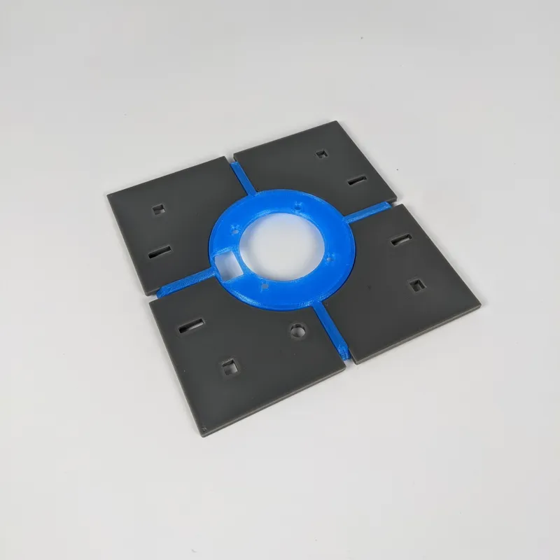
- 1 x Bottom_1: This part has an extra hole for the power cable
- 3 x Bottom_2
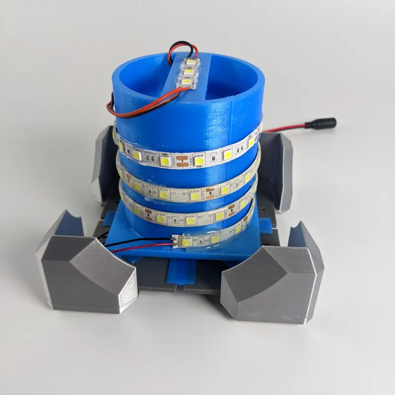
- 1 x LED_Holder_Base
- 1 x LED_Holder
- 4 x Top
- 8 x Wall_1: Print with 100% infill to prevent light bleeding through
- 32 x Peg (Print extras. Trust me.)
- 40 x Cap_Insert
- 8 x Corner_1
- 8 x Corner_2
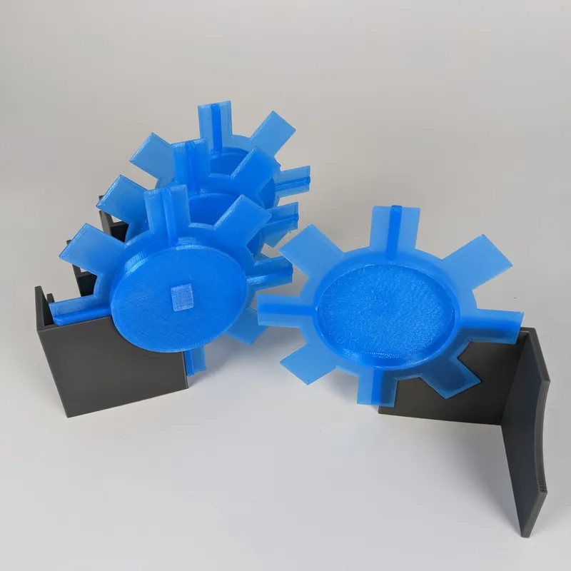
- 5 x Glow_1: Print these with supports
- 1 x Glow_2: Print this with supports
- 5 x Cap
Build Instruction:
- Assemble the eight corners using 4 x pegs as a guide. Go easy in application of glue to avoid squeeze out. Glue toward the inside of the corners
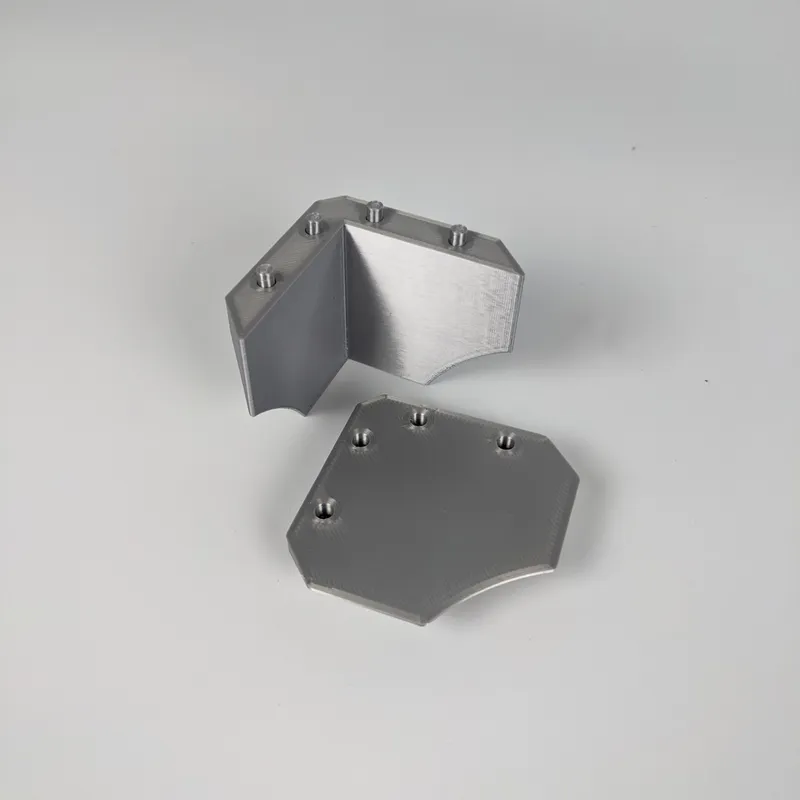
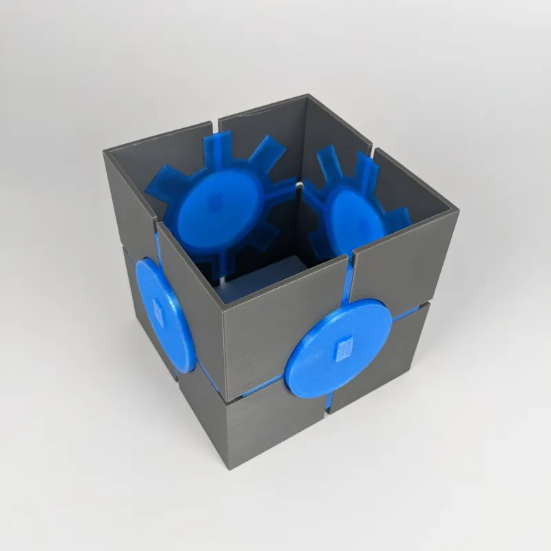
- Glue the top side using 4 x Top and 1 x Glow_1 parts
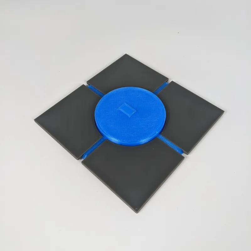
- Glue the bottom side using 1 x Bottom_1, 3 x Bottom_2, and 1 x Glow_2 parts
- Glue the corners to the bottom using the Jig to compensate for the wall thickness.
- 4 x Glue Glow_1 to Wall_1
- Glue the remaining 4 x Wall_1 to make the shell
- Place the Top side on top of the cube. Note that it will not fit from the bottom and must be in place before gluing the top corners
- Glue the four top corners to the cube
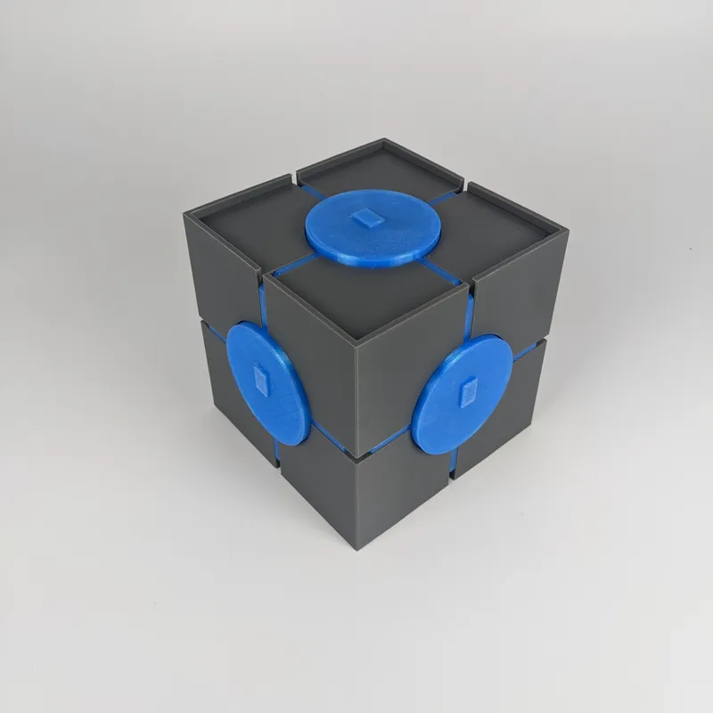
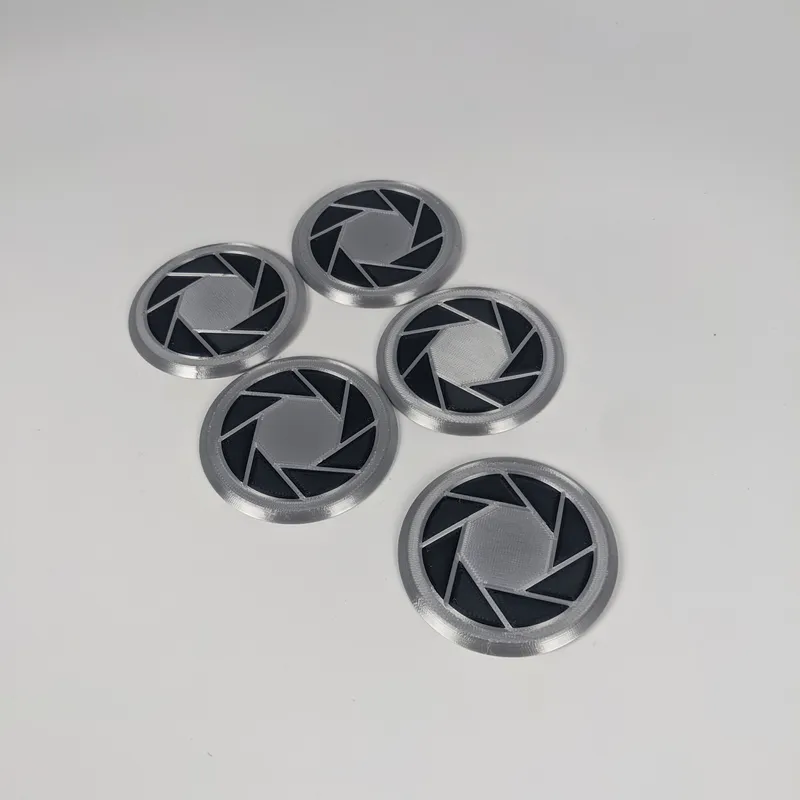
- 5 x Glue Cap_Inserts into the Cap
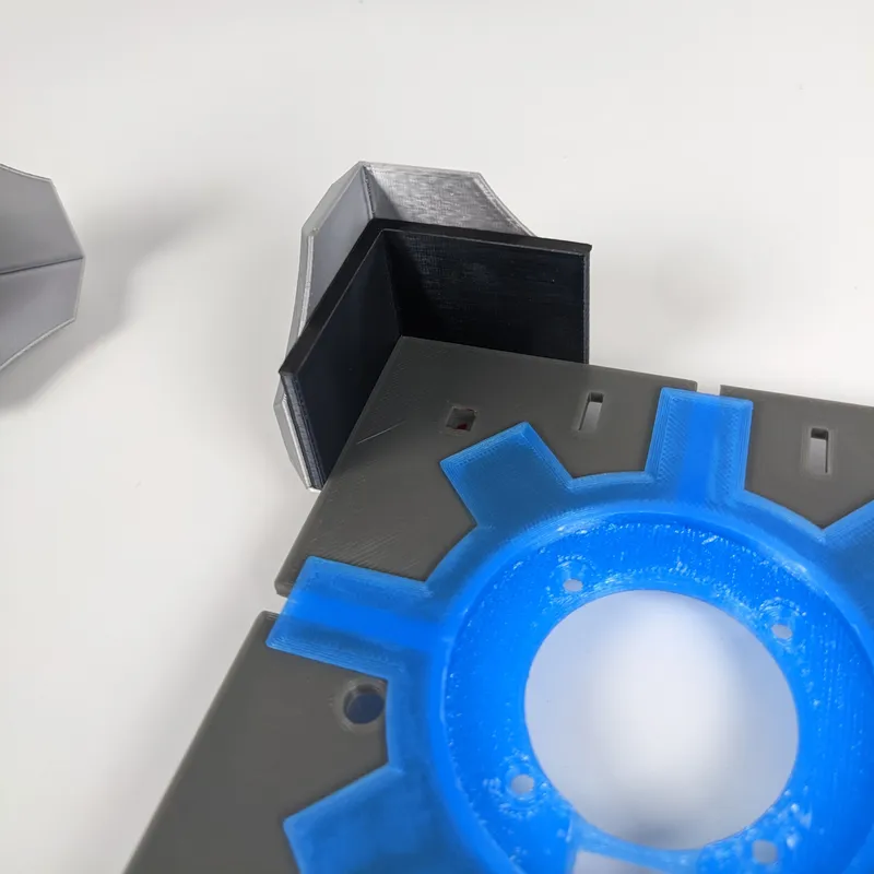
- Glue 5 x Cap and 8 x Edge_Block to cube
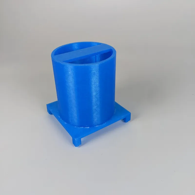
- Glue LED_Holder to LED_Holder_Base
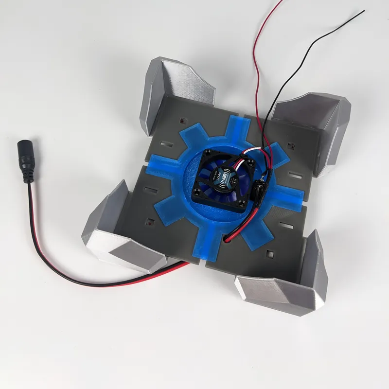
- Attach fan and switch to bottom side
- Thread the 5.5mm female connector through the hole and solider positive to switch. Switch can be wired to the negative side as well.

- Solder the positive of the fan and a length of wire (this will make soldering LEDs easier) to the other leg of the switch.
- Solder the negative of the fan and a length of wire (this will make soldering LEDs easier) to the negative of the female connector. Cover with shrink tube.
- Wrap 3-4 feet of LED strip around the LED_Holder.
- Apply hot glue to edges of LED strip because the adhesive strip it comes with will fail
- Cut off three LEDs and hot glue them to the top of LED_Holder. Using two more lengths of wire connect them to the end of the longer strip.
- Optional: Solder in another section of 3 LEDs and using hot glue stick them under the beam on top of the LED_Holder to shine down
- Time to test
- Place LED_Holder_base into the bottom side of the cube. Do not glue
- Solder the two previously left wires to the LEDs.
- Attach to power and turn flip the switch
- If everything works, lift the LED_Holder_base out of the cube, apply glue to legs and glue in place
- Place cube over the LEDs, on top of the bottom side. The corners may be a tight fit.
- Glue the remaining 4 x Edge_Block to the bottom side and not the rest of the cube so it can be opened in the future.
- Enjoy!
Tags
Model origin
The author hasn't provided the model origin yet.


