Improved Wandering Hour Clock

Description
PDF
Introduction
How to read: The current hour points to the current minute.
This is a rework of the wandering hour clock by clockspot: https://www.printables.com/model/69885-wandering-hour-clock
I changed the mechanism, they did the concept and look.
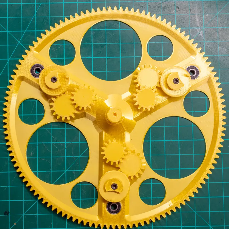
The clock has a diameter of 38 cm.
A print bed of at least 200 mm x 200 mm is needed for the printed parts!
You may need to split the MinuteArc.
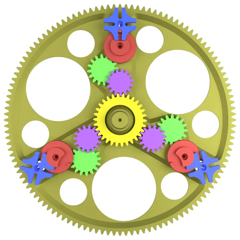
The mechanism makes use of a Geneva drive to rotate the hour wheels.
Here is how the mechanism works:
Additional Hardware
1x Ikea Bondis Clock. Check your local Ikea site for availability.
Ikea US
Alternatively you can get them used. Look on eBay or your local classifieds site.
| Screws | Amount |
|---|---|
| M3x6 mm | 14 |
| M3x18 mm | 3 |
| M3x4 mm | 3 |
| M3x8 mm | 1 |
| Bearing | Amount |
|---|---|
| 695 5x13x4 | 12 |
| 6002 15x32x9 | 1 |
Clock Movement:
I tested these two movements and can confirm they work:
UTS 800 (former Junghans W 838) High Torque, 16 mm shaft length 800 355
UTS 800 (former Junghans W383) 16 mm shaft length 800 055
If you're getting your movement somewhere else make sure to buy one with a euro shaft and the correct length. Compare it with the pictures on the site I linked.
EDIT: I installed a normal (not high torque) clock movement, and it seems to work just fine. For the easiest installation I recommend a 16 mm movement with a euro shaft (with thread and the small round nut). The original Ikea movement is just a little too weak.
Optional: Cardboard stock with a minimum of 350x350 mm, A2 for example. This will be used as the new background color.
It is also possible to remove the numbers on the original backing with acetone. This way you get a matte black background. Thanks to matemaciek for discovering this!
Tools
You need to drill various sized holes into the plastic bondis clock frame. You should be able to make holes in the following sizes: 3mm, 10mm and 18mm. A step drill works great.
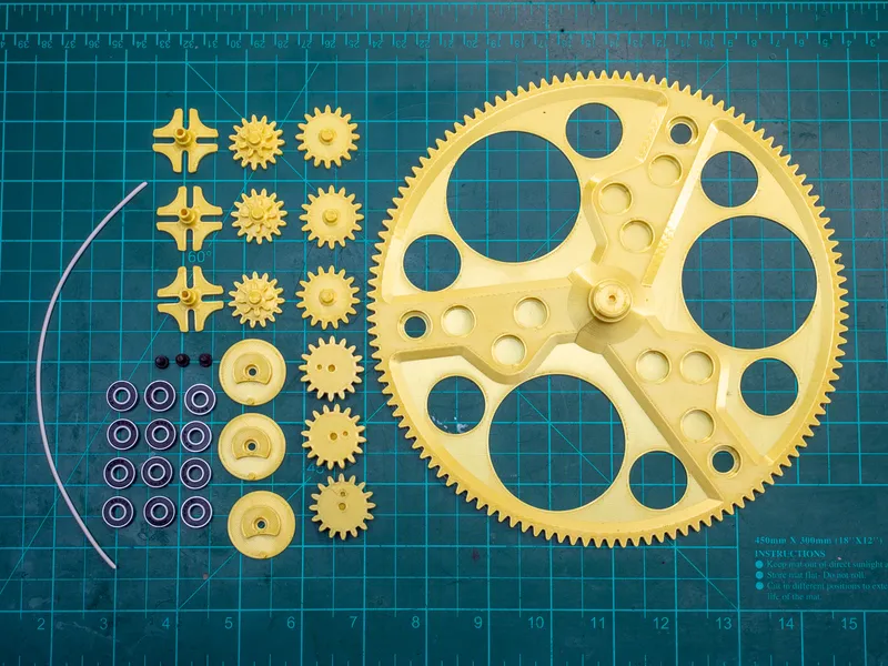
Printed Parts
Print all parts in the specified amounts. No supports are needed. I used a 0.4 mm nozzle, PLA and a 0.2 mm layer height.
| Part Name | Amount |
|---|---|
| Central_Gear | 1 |
| CentralGearHolder | 1 |
| CentralGearRetainer | 1 |
| ClockMovementGear | 1 |
| ClockMovementSpacer | 1 |
| Drill_Template_Standoff | 1 |
| Standoff | 4 |
| Geneva_Gear_Central | 1 |
| Geneva_Gear_1 | 3 |
| Geneva_Gear_2 | 3 |
| Geneva_Gear_3 | 3 |
| Geneva_Driver | 3 |
| Geneva_Driven | 3 |
| NumberWheelWasher | 3 |
Do a color change on the parts below for more contrast.
| Part Name (color change) | Amount |
|---|---|
| MinuteArc | 1 |
| NumberWheel_1_4_7_10 | 1 |
| NumberWheel_2_5_8_11 | 1 |
| NumberWheel_3_6_9_12 | 1 |
Assembly Instructions
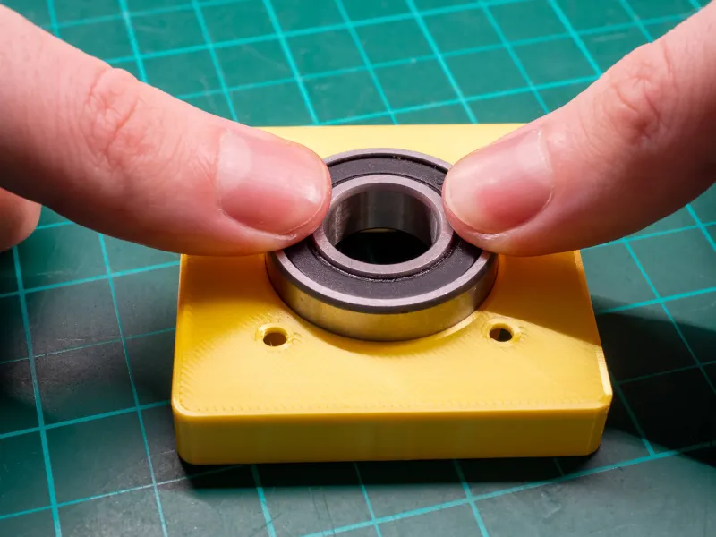
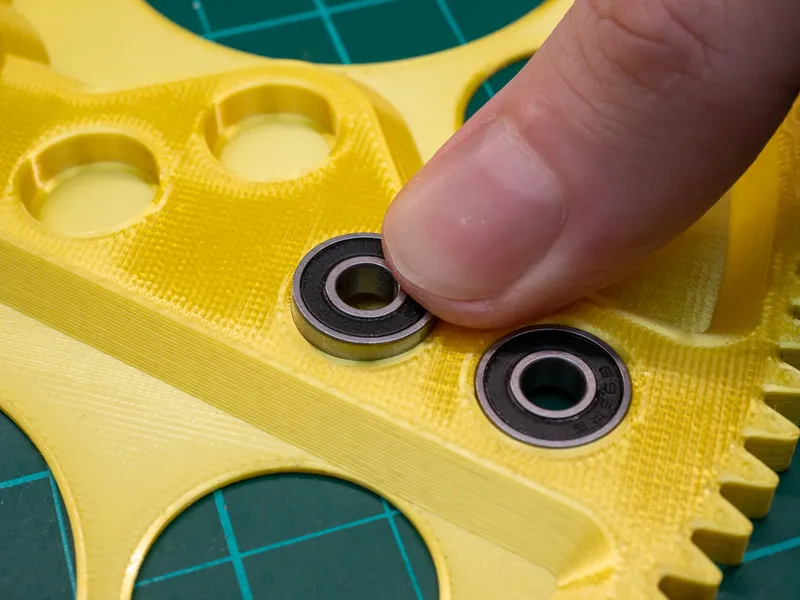
CentralGearHolder Bearing Insertion
Press the bigger bearing into the CentralGearHolder. The fit is really tight, you may need to use a vise.
 | 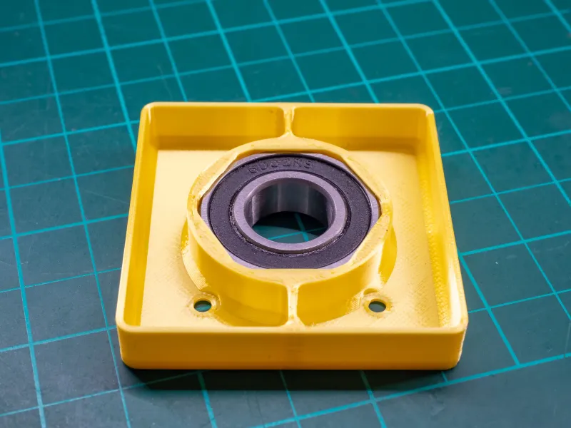 |
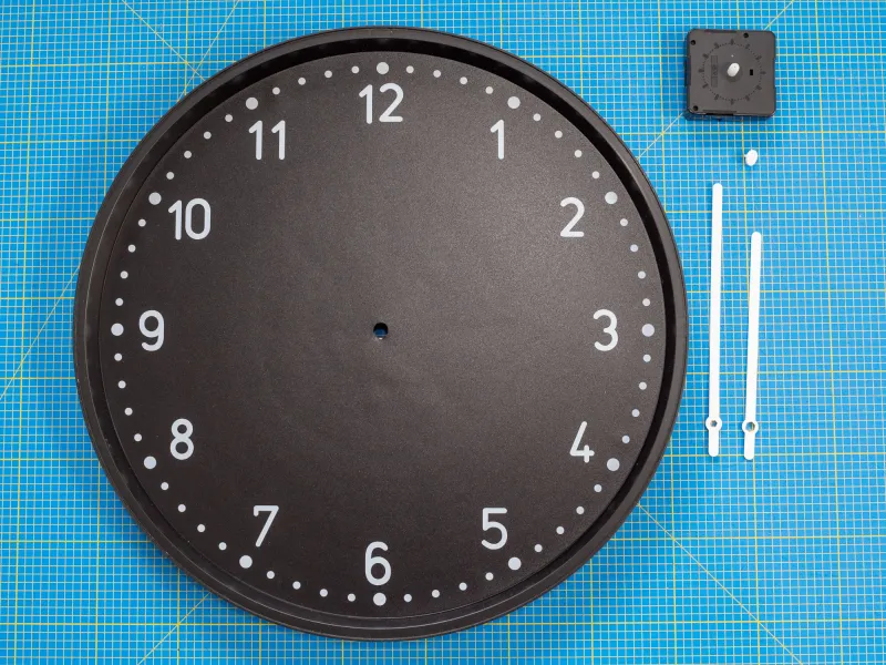
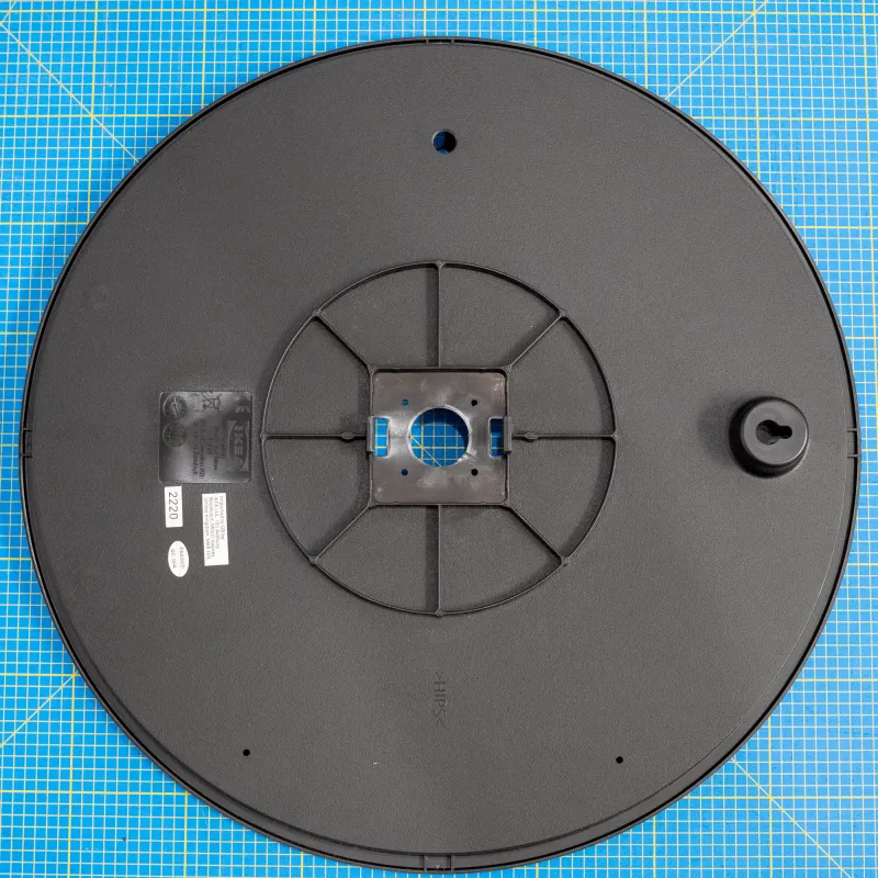
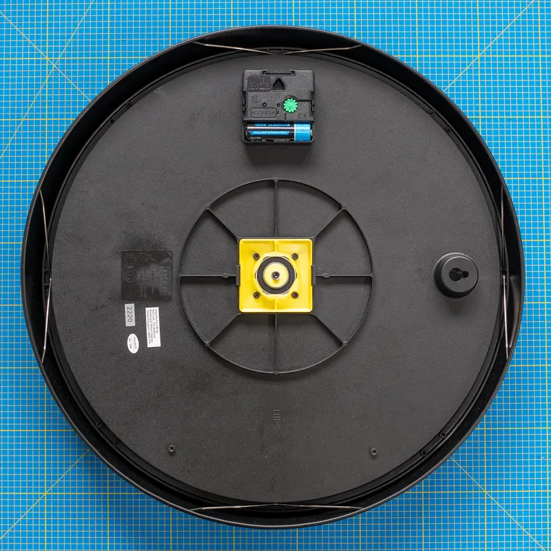
Bondis preparation
Separate the inner plastic piece from the outer frame by taking the steel clips off. Put the metal frame and the glass somewhere safe.
Remove the clock hands and the clock movement. You will not need these as we will be using a different, stronger clock movement.
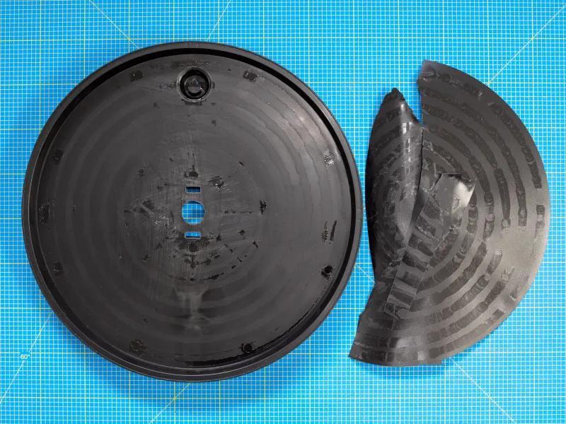
Then peel off the sticker with the hours on it. Or don't, if you like the look.
There is also the possibility of removing the numbers with acetone.
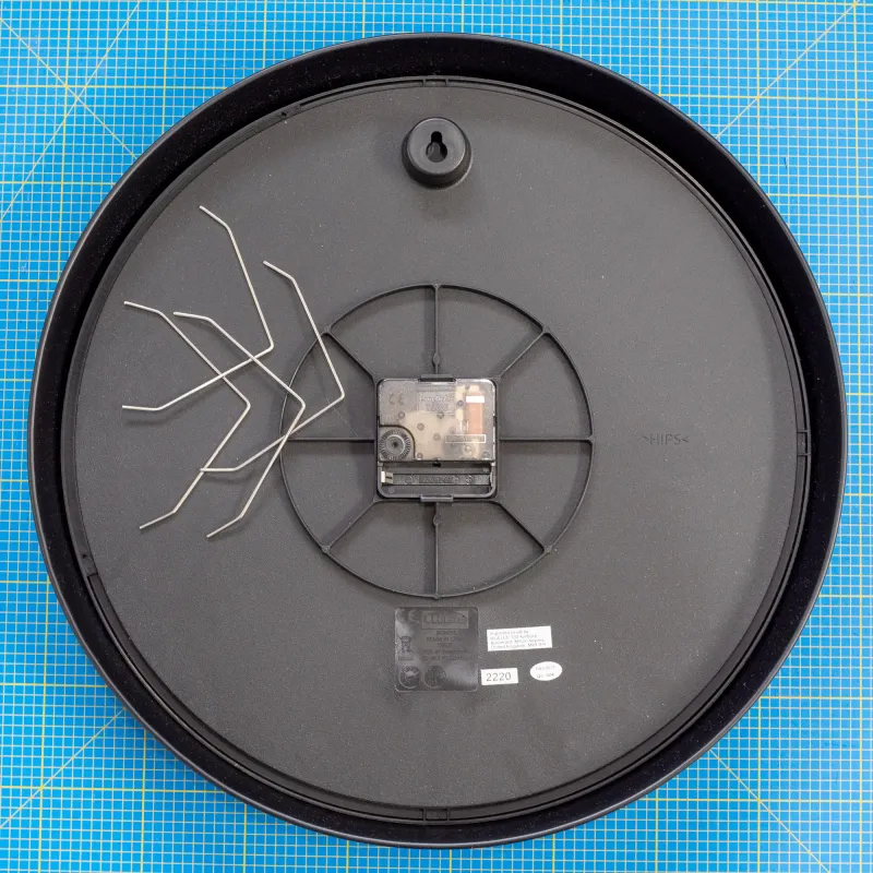 |  |  |
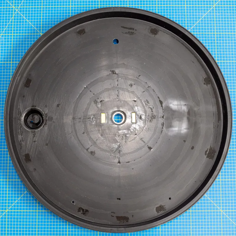
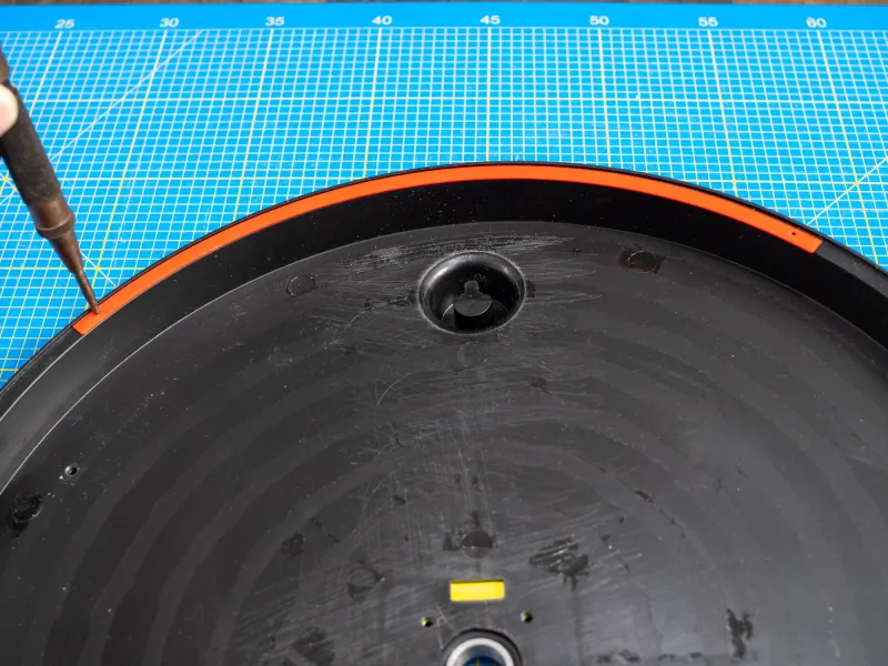
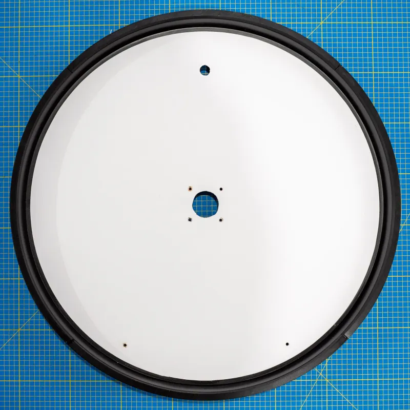
Holes
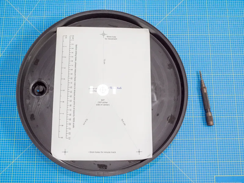
Print the drill template under “Other Files” (measure the rulers to make sure it was printed correctly).
Orientate the clock with the original wall mount to the left.
Lay the drill template onto the clock with the center bearing hole aligned to the center hole of the clock. Use a light source behind the clock to make it easier.
Mark all the holes and drill according to the size on the template.
 |  |
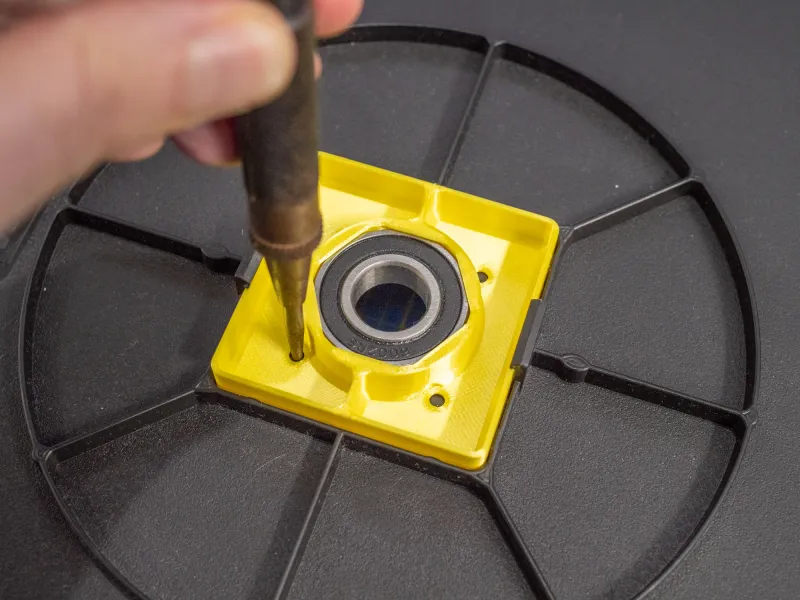
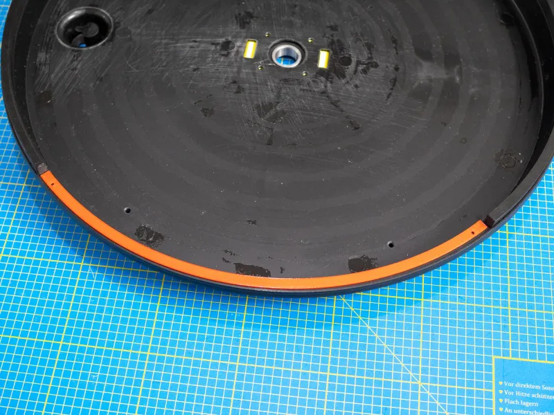
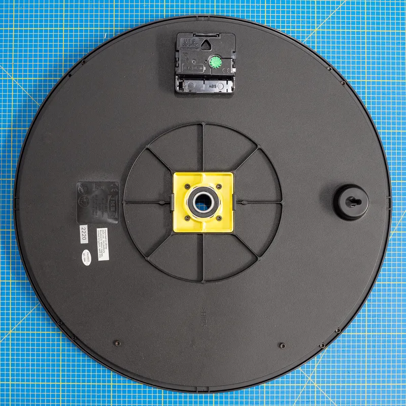
Insert the CentralGearHolder into the clock and mark the holes. Remove the CentralGearHolder and drill four holes with a 3 mm drill bit.
 |  |  |
Edge Standoff
Take the Drill_Template, put it across the top of the clock, mark the two holes and drill two holes of 3 mm.
Take one Standoff and fasten it to the edge with M3x6 mm screws.
Repeat this step with all four Standoffs.
 |  |
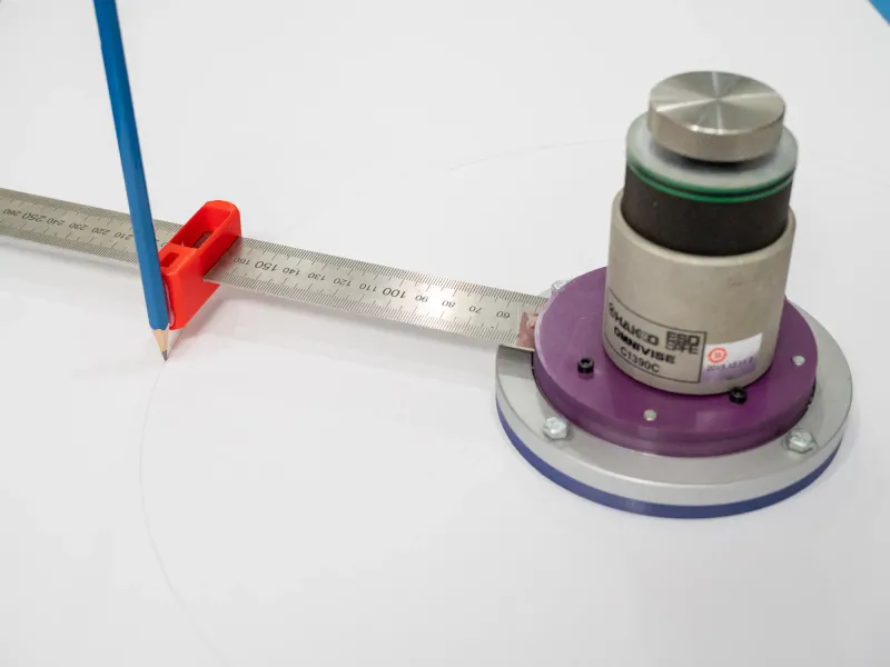
Cardboard Disc
Cut a 340 mm cardboard disc out of a color of your choosing. I built a simple rig to draw a circle and then cut it out with a scalpel.
 | 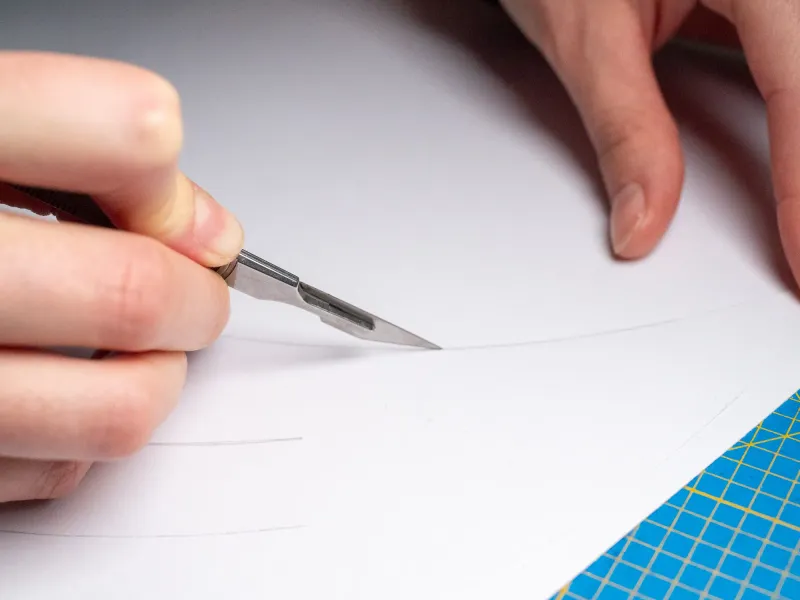 |
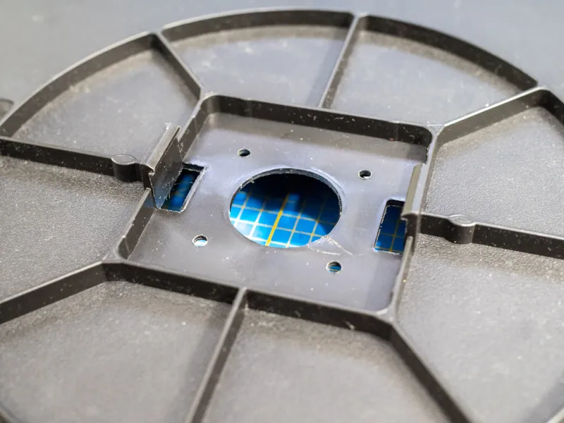
Lay the circle on the clock and cut the holes for the MinuteArc through (use a light source behind the clock again to see where the holes are exactly). Do the same with the clock movement hole and the central gear holder holes.
Use M3x6 mm screws to fix the MinuteArc to the clock.
Fasten the Geneva_Gear_Central from the back with four M3x6 mm screws.
 | 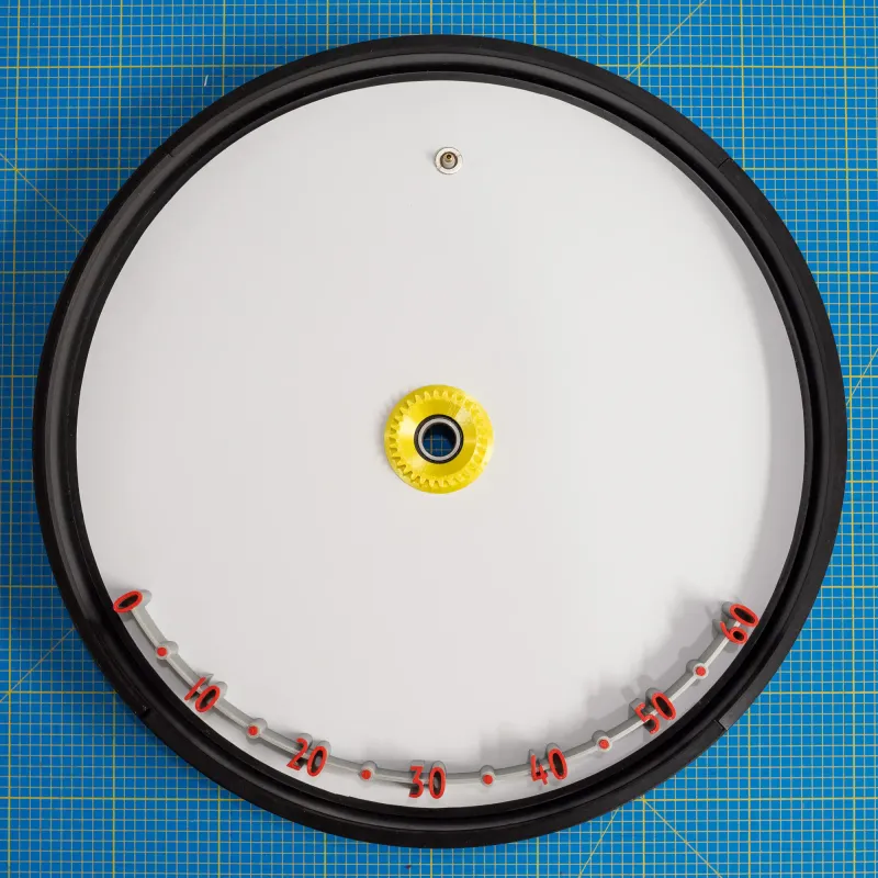 |
Clock Movement
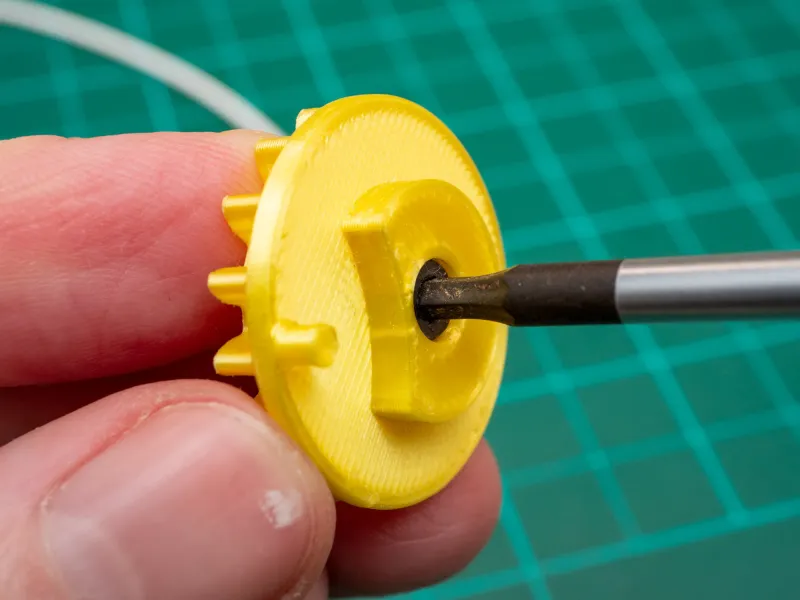
Use a soldering iron on low heat to press the hand nut, that came with the movement, into the ClockMovementGear. Alternatively, use a press fit.
 | 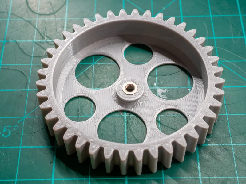 |
Place the ClockMovementSpacer onto the clock movement.
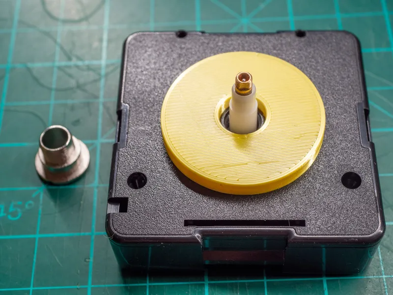
Stick the movement with the spacer through the clock and secure it with the central nut from the other side.
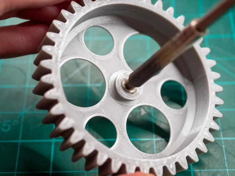
Rotate the ClockMovementGear onto the clock movement shaft. I highly recommend gluing it in place. Otherwise, it will wiggle itself off the shaft. I used blue thread-locking fluid.
Central_Gear Assembly
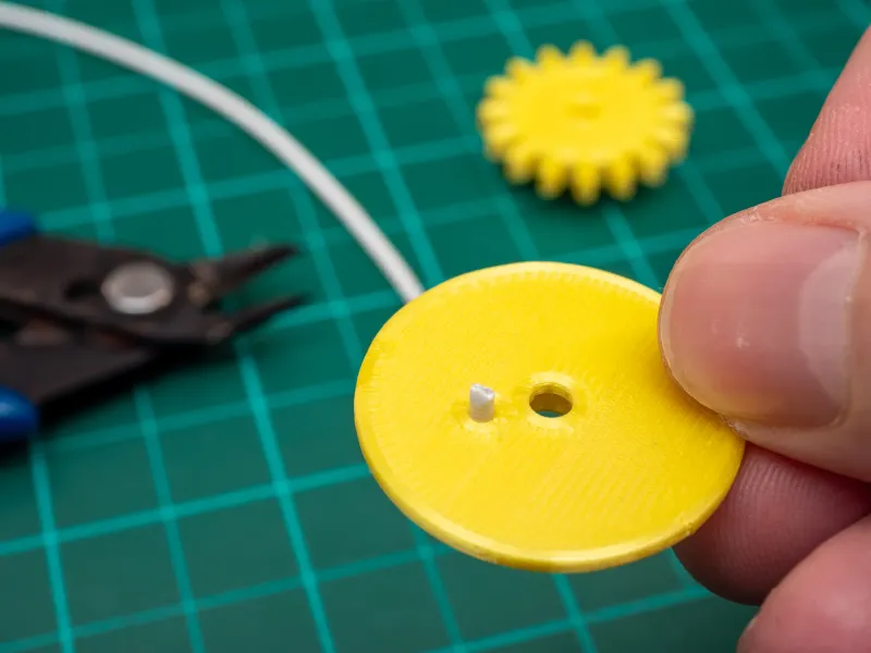
Take some 1.75 mm filament and cut off three pieces about 4 mm long.
Press each one into the small hole on the Geneva_Gear_3.
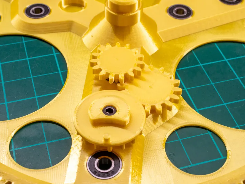
Fix the Geneva_Driver onto these gears with a M3x4mm screw. Make sure to align the little piece of filament with the hole.
 |  |
Press the small bearings into the Central_Gear.
Insert the gears. Start with the Geneva_Gear_2.
Continue with Geneva_Gear_1. Then insert the driver gear you assembled earlier.
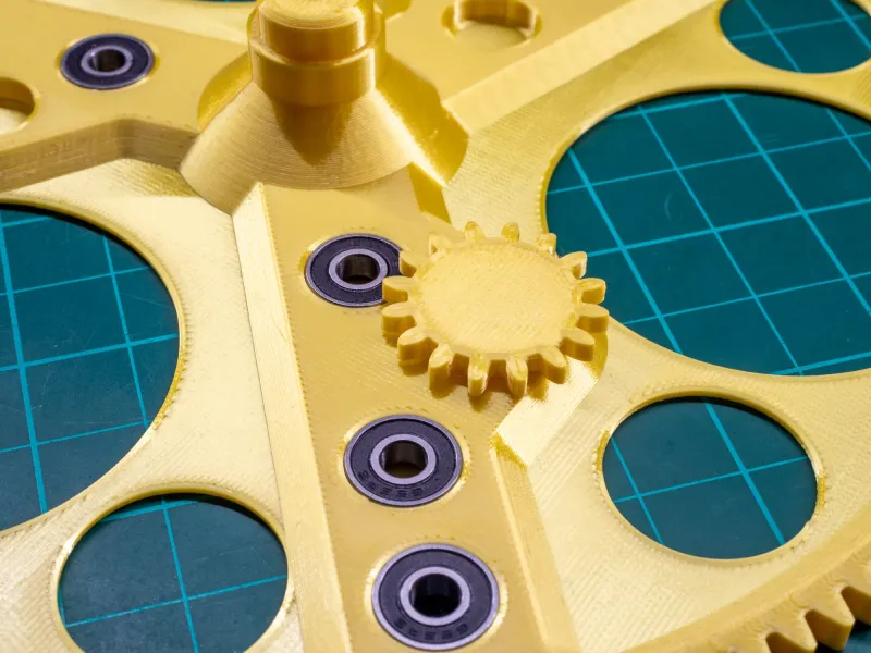 | 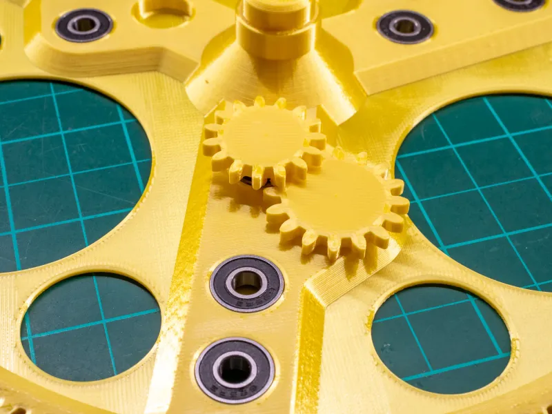 |  |
Repeat this for all 3 gear trains.
Insert the Geneva_Driven in the bearing. Slip a NumberWheelWasher over the part sticking out on the other side. Then use M3x18 mm screws to gently fix the NumberWheels to the Geneva_Driven part. Notice the orientation in the image.
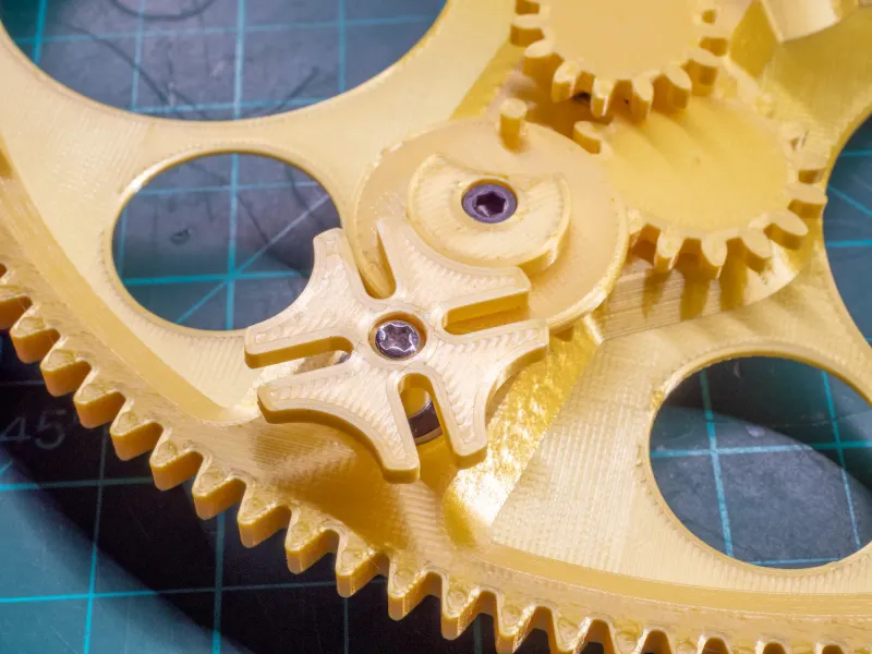 | 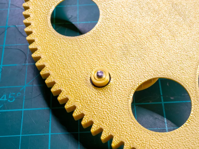 | 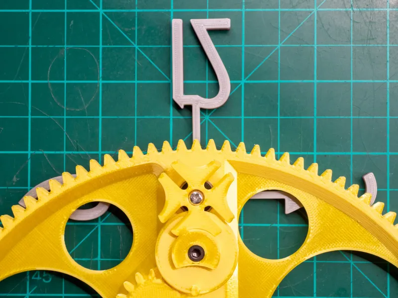 |
Bring the Numberwheels in the position as shown. Use the second image below as a guide for the Geneva_Driver. Afterward slide the Central_Gear into the central bearing. You may need to wiggle it a bit for the teeth to engage. The Geneva_Driver that is pointing up needs to be positioned behind the ClockMovementGear and the other two pointing at minute 0 and 60.
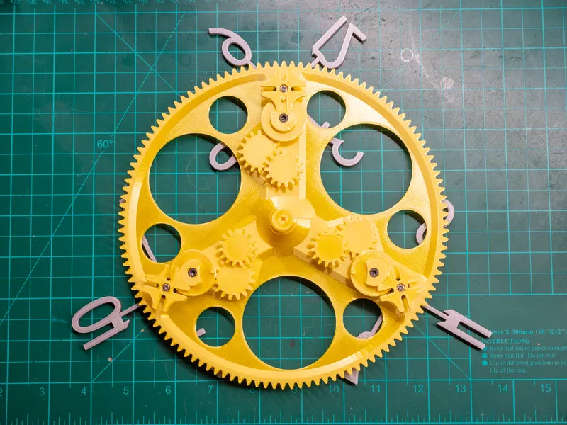
Use this image as reference for the position of the Geneva_Driver. This way the number wheels will only turn exactly at the top of the clock.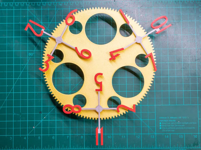
Secure the Central_Gear from the back with the CentralGearRetainer and a M3x8 mm screw.
Insert the clock back into the metal frame with the glass. Secure everything with the metal clips.
Congratulations, your new clock is done. You just need to set the time with the little wheel on the movement and mount it on the wall with a nail. Hang the clock by the rim of the bondis. The movement will not turn if you mount the clock with the included hook of the movement!
Troubleshooting
The clock is not turning at all.
Insert a fresh battery into the movement. Test the movement by removing the movementgear and sticking a piece of tape on the shaft. The tape should move. If it does not, the movement may be defective.
Also, if you hung your clock by the hook on the clock movement, hang it from the rim.
The clock starts to turn and then stops after some time/the clock does not keep time.
With a clock of this size, friction is everything. It must be minimized. Remove the movementgear and feel the friction by moving the central gear by hand. Any unusual resistance, such as a section with more friction (e.g. when the geneva mechanism engages), needs to be addressed and may be the reason the clock is not running.
I am aware that some of the tolerances are very small, but it is hard to account for the tolerances of other printers when the parts need to interface with bearings.
Be sure to print with elephant's foot compensation and sand down any edges that add friction.
Tags
Model origin
The author remixed this model.

Differences of the remix compared to the original
Same aesthetic but completely redesigned mechanism.