First Layer Calibration Shapes - Customizable
Gosh, first level seams to be wrong :-( Well, what can I do... ;-) For first level printing height calibration and…
17
587
0
1755
updated May 18, 2020
Description
PDFGosh, first level seams to be wrong :-(
Well, what can I do... ;-)
For first level printing height calibration and optimization I "designed" two simple shapes.
- Simple one is just printing complete area defined
- Other model just place a selected number of connected measurement points to the sheet. That's much faster and should give you a good setting for z-level calibration already.
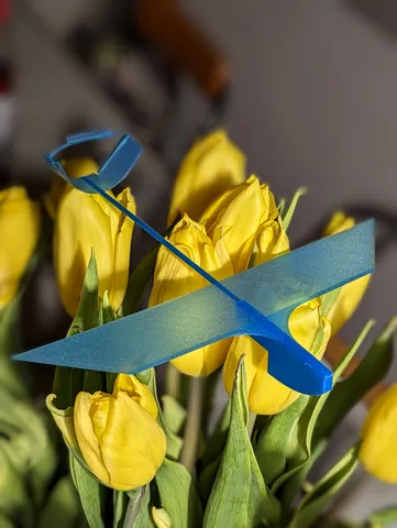
Update 31.07.2022
Attach a mini handle, to make removing the print much easier.
Print instructions
In provided OpenSCAD file (.scad), you can adjust settings to match your printer, like:
- print dimension in X/Y
- first layer height
- number of measurement points to print
- full first layer, or measurement points only
- ...
How I used it:
- get a rough first z level value you think usable (live adjust z)
- make a print & check surface.
Are there holes because you print to high?
Is the surface quite rough/thin because you print to low? - adjust z level via "live adjust z...".
Therefore you might go up/down by 0.050 mm steps for the next print. - continue surface evaluation and z-level adjustment till it matches your expectation.
- I guess maybe 3 to 5 prints should do the job if your starting z-level is already in a good range.
- In case you are curious if you complete print plate is well usable with your "measured" z-level - AND you have some hours print time left, then go and print complete first level ;-)
I used given settings for my MK3S MUU2S printer.
Happy printing! :-)
Things to improve
- Actually it would be nice to have a label (down left corner for example).
Therefore a dedicated place to write z-level used for this print. - Add maybe some more interesting shapes.
- Add simpler shapes for (even) shorter print time.
- Add mode to define where to place the measurement points. Currently they are oriented in the "middle" of a pattern. Edges would be interesting as well I guess...
Tags
Model origin
The author hasn't provided the model origin yet.