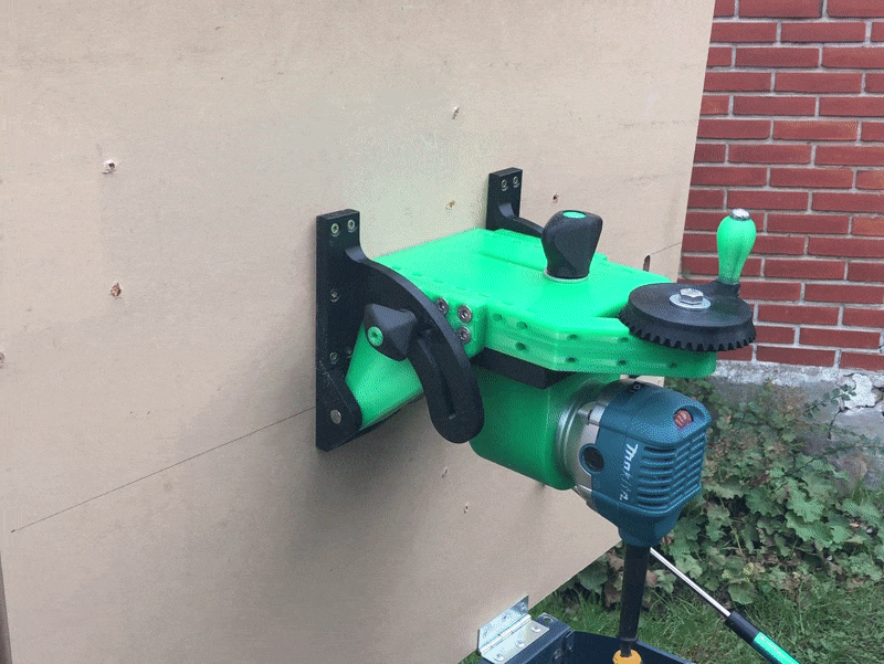
Tilting router lift

Description
PDFA heated insert version of http://www.thingiverse.com/thing:3166165
Hardware:
** if making the main body in 2 parts you will need 2 m6 by 25 cap head screws for attaching the top to the bottom body sections
* M10 threaded rod for the main screw that will pull the sliding dovetail up and down
* m8 x 50 bolt and nut for attaching the large gear to the main body
* M8 x 50 partially threaded bolt for attaching the height adjustment knob to the large gear
* m10 washers as spacers for the small gear
* 2 - m6 x 45 bolts for the locking knobs on each side
* m6 heated inserts (I designed for these m6 x D9 x 6L https://www.aliexpress.com/item/2255800046675771.html)
* 14 - m6 x 20 flat head bolts for the hinge plates to attach to the main body
* 5 - m6 grub screws (for adjusting the tension on the dovetail)
* 3 - m6 x 30 cap head bolts for the 3.5 inch router holder
* 4 - m6 x 30 cap head bolts for attaching the 3.5 inch router holder to the dovetail slide
* M8 x 50 bolt for height adjustment locking knob
* 2 - 10mm pins for the hinges
* wood screws for mounting
From the original creator:
Tilting Router Lift by brianfroelund is licensed under the Creative Commons - Attribution license.
http://creativecommons.org/licenses/by/3.0/
Tilting router lift inspired by [Matthias Wandel](https://woodgears.ca/router_lift/)
It is designed to handle all commonly available routers. The router holder is a separate part that can easily be drawn for your specific router. I'm using it with a Makita RT0700 series trim router.
Specifications
---------------------
* 80mm (3.15") depth range
* 45° tilt range
* Can support 0-100mm (0-4") diameter routers (will design holders on request)
* Each turn on depth handle changes depth of cut by 3mm
# Details
## Hardware
This build requires quite a bit of hardware. I've designed the router lift in metric so all the hardware is also metric. The bolts are DIN standard, not ISO.
(converted to imperial using https://www.dot.ny.gov/main/business-center/engineering/specifications/english-spec-repository/bolt_table.pdf)
* 1x 180mm(7inch) M10-1.5(7/16inch) threaded rod
* 2x 10mm (25/64inch or about 3/8 inch) diameter 50 mm long shaft
* 2x M10-1.5(7/16inch) nut
* 4x M10(7/16inch) oversized washer
* 1x M8(5/16inch) nut
* 1x M8(5/16inch) 40mm(1.574803 inch) partially threaded bolt (for large gear)
* 2x M8(5/16inch) 50mm(2 inch) partially threaded bolt (for gear knob and depth lock knob)
* 1x M8(5/16inch) washer
* 27x M6(1/4inch) nut
* 4x M6(1/4inch) grub screw (dovetail slide adjustment)
* 3x M6(1/4inch) washer
* 3x M6(1/4inch) 25mm(1 inch) socket head bolt
* 14x M6(1/4inch) 20mm (0.7874016 inch) flat head socket bolt
* 2x M6(1/4inch) 45mm(1.771654 inch) socket head bolt (tilt lock knobs)
* 8x M6(1/4inch) 40mm(1.574803 inch) socket head bolt
* 18x wood mounting screw
## Printing
I've have spend quite a bit of time altering the design to avoid need for support when printing.
My router lift is printed in a mix of PLA (Green) and PETG (Black). I haven't logged my print settings for all components but underneath you will find my print settings for the essential parts. All the STL files are shown facing the direction I have printed them.
* Hinge plates: 50% Infill, 8 top/bottom layers, 6 perimeters (12 hours)
* Gears: 20% infill, 4 perimeters, with support on build plate only, (5 hours)
* Dovetail rail: 50% Infill, 8 top/bottom, 6 perimeters, with support on build plate only, (42 hours)
* 65mm router holder: 50% infill 8 top/bottom, 6 perimeters. no support
## Table and Fence
The table is built from a not that old but really bad table saw. I removed the original table, cut a hole on one side and fitting a piece of 25mm mdf tabletop on it instead.
The fence is made from birch plywood and the sacrificial part of it is made of laminate flooring that I had left over. Knobs are all 3d printed. I use [ljon's dust extraction port](https://www.thingiverse.com/thing:1789688) which make it easy to plug in a 100mm flex tube for dust collection. I don't have my dust collection system set up yet so i made a adapter for it to fit my shop vac until I get the other system set up.
## Change log
2019-01-12: Updated hinge locks to allow for 10 degrees of movement beyond 90 degree upright position. This requires special mounting for the rail not to hit the table
2018-12-26: Updated the rail to be slightly shorter and added the ability to split the rail into two parts for smaller print beds.
2018-11-26: Added beefier version of the large gear as gear arm snapped on mine because i walking into something when moving the lift mounted to the table. Started a change log and assembly section.
Tags
Model origin
The author hasn't provided the model origin yet.


