Core XY Cartesian Motion System

Description
PDF
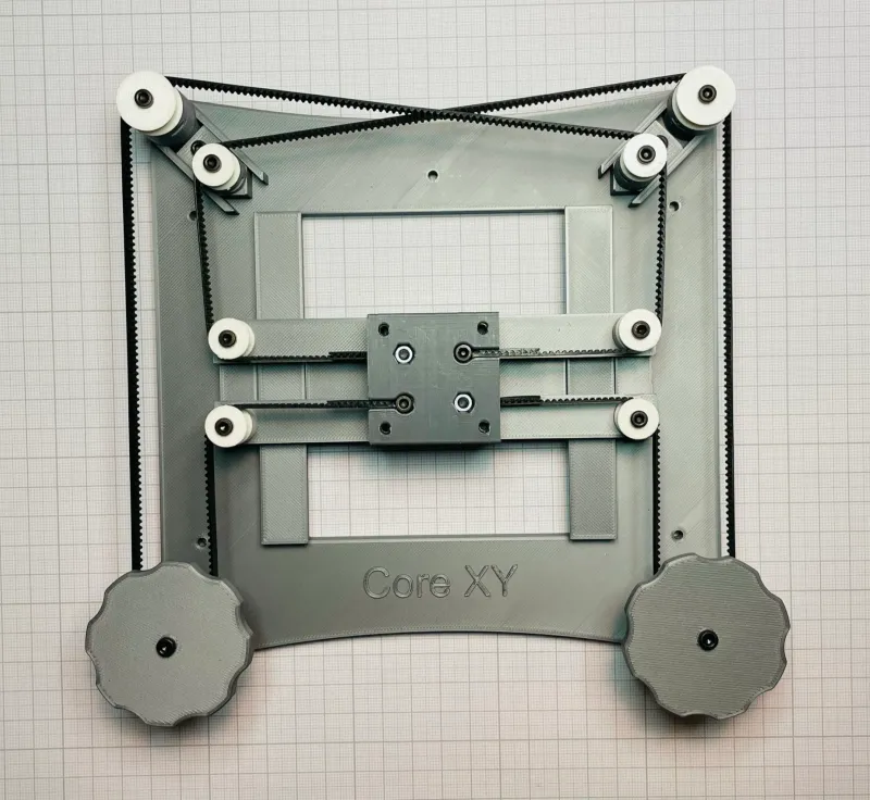
I have designed this Core XY Cartesian Motion System in Fusion 360 and printed it using my PRUSA MK3S. I have also included for fun accessories such pen holder and miniature milling table. You will only need to get 3 length M3 SHCS, M3 Hex Nuts, two small rubber bands, a marker and standard 6 mm GT2 belts to complete the assembling.
Here is how it is working; rotating both KNOBS in the same direction results in horizontal motion. Rotating both KNOBS in opposite directions result in vertical motion.
For more information, read Ilan Moyer in his excellent site (coreXY.com)
Hoping that my Core XY system will be used for educational purpose and enthusiasm makers.
Updated 2023-01-08
The maximum travels are 75 mm on X axis and 70 mm on Y axis.
Thank you Kyle for asking this detail.
WARNING:
There is only 0,1 mm tolerance between tapered rails and SLIDES, also parts have to be flats for the CORE XY system to work properly. I would recommend to print only SLIDE X and SLIDE Y first and try assembling them. If you have good results then continue, otherwise tune and calibrate your 3D printer.
PARTS:
- FRAME
- SLIDE Y AXIS
- SLIDE X AXIS
- KNOBS-TIMING PULLEYS
- TENSIONERS
- PULLEYS
PARTS ACCESSORIES:
- PEN STAND
- PEN HOLDER
- BED
- MINIATURE MILLING TABLE
PREPARATION:
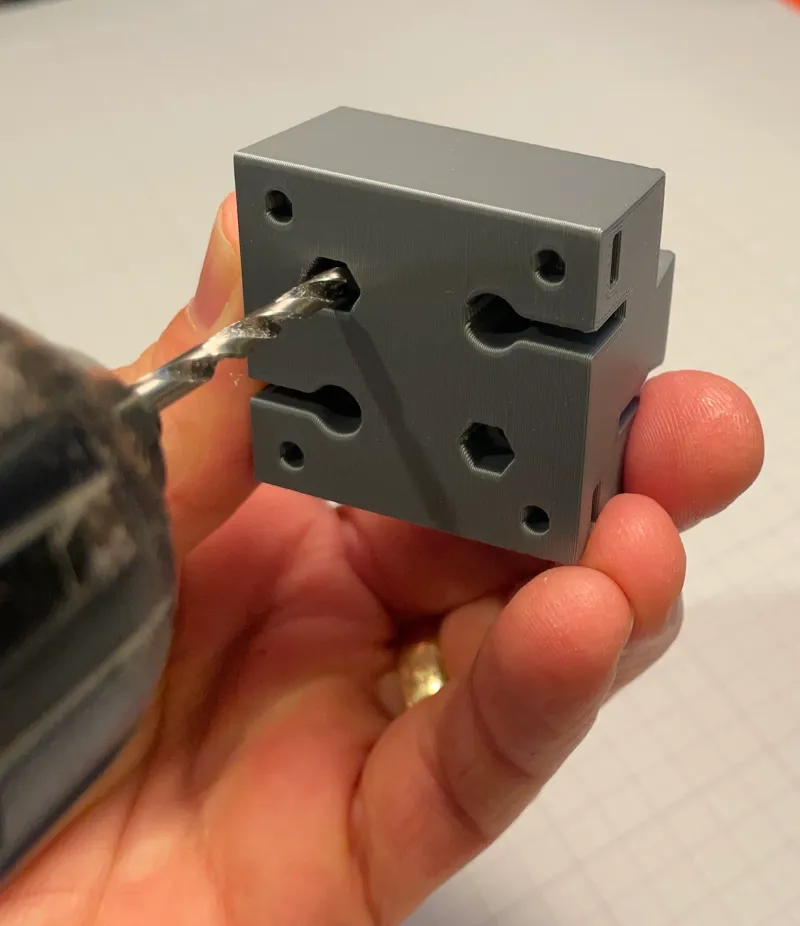
After printing all the parts, remove all supports where needed and clean parts, take your time with the pulleys. First, drill 3,3 mm on all part holes used for 3 mm screws. Rectangular openings are for Hex Nuts, they must be free of obstructions for easy nut assembling.
ASSEMBLING
Note:
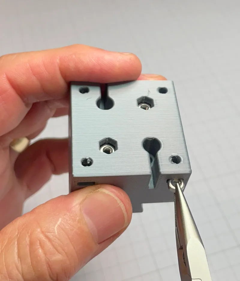
Install all Hex Nuts into rectangular openings on all parts before going to the next steps. Insert the Nut with a plier and use a thin blade to push it until it align with 3,3 mm hole. If you go too far, push it back from the other end.
As a general rule regarding screwing M3 SHCS, I would suggest for static parts only apply additional ¼ turn for tightness. For motion parts such pulleys, unscrew by ¼ turn when proper tightness is reached. This will make a big difference for smooth motions and avoid breaking parts!
When I refer to left or right in instructions, the frame is oriented such you can read CORE XY. ( not upside down). The KNOBS positions are closer to you. ( As shown on most pictures)
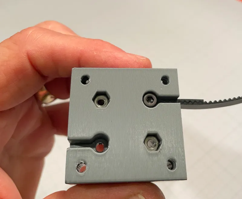
SLIDE X AXIS: Square shape with most complexity
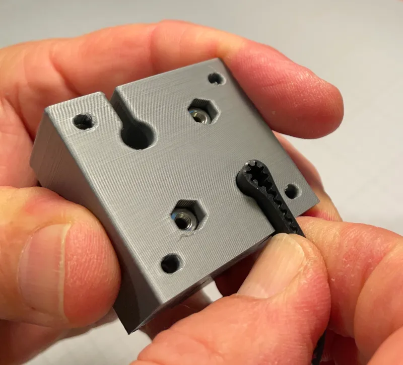
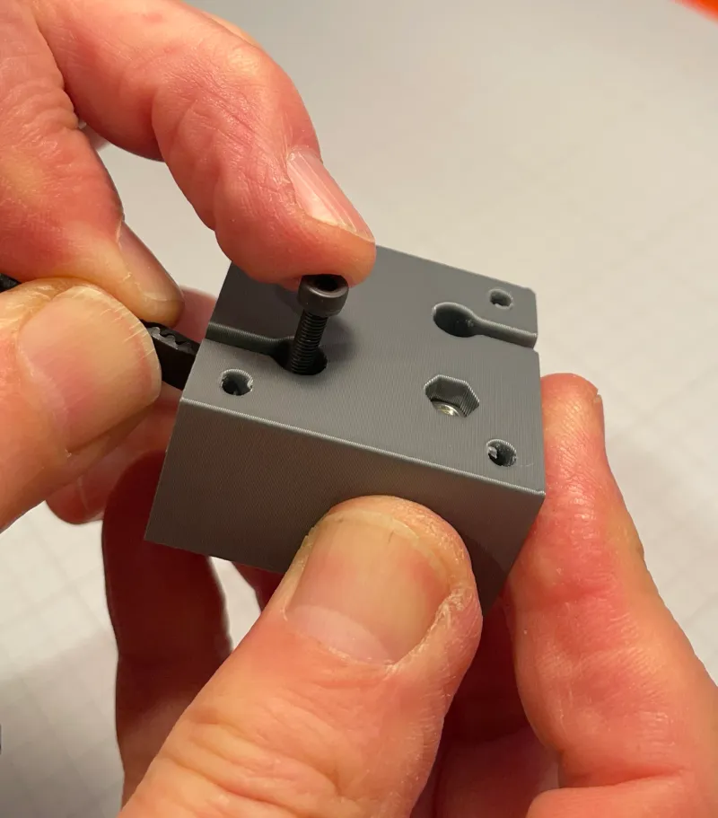
For the two belts installation, insert temporarily a longer screw and screw Hex Nut a few turns and pull screw head to secure Hex Nut all way in. Remove temporary screw, bend belt end and push it into groove. Push belt on SLIDE X AXIS side to provide room for M3 x 16 SHCS insertion. Do not overtight to prevent belt damage. Repeat these steps four times ( two on each side). For you information, its the same design concept used in the PRUSA printer tensioner. There was no need to reinvent a great idea. Make sure belt teeth is pointing in the correct side, look at the pictures.
SLIDE Y AXIS: Rectangular shape
Install PULLEYS only on left side first. Notice that belts are on a different high. The taller PULLEY is closer to the KNOB on the left side. Use 4 M3 x 25 SHCS for PULLEYS. Then, insert the SLIDE Y AXIS into the FRAME rails from the KNOBS side.
FRAME:
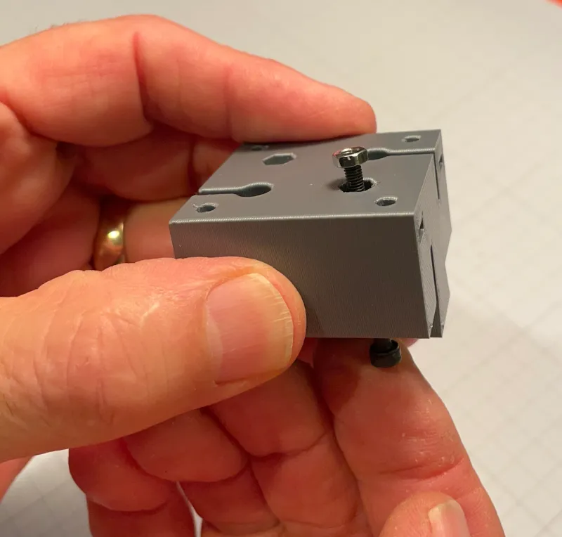
Its time to install the two KNOBS, notice that the thinner KNOB unit is installed on the left on the higher post. Larger diameter PULLEYS are installed in upward corners, both are identical. Screws: 2 M3 x 30 SHCS for KNOBS and 2 M3 x 16 SHCS for corner pulleys.
TENSIONERS: Have different post height for correct belt position
Install thinnest PULLEYS, screws: 2 M3 x 16 SHCS. Install TENSIONERS on the FRAME, TENSIONER with shorter post goes on the left. Insert M3 Hex Nuts into FRAME into rear slot and insert screw from the front, screws 2 M3 x 16 SHCS. Do not tights yet, allow the TENSIONER to freely move between the side ribs.
FINAL ASSEMBLING: We are almost done
Insert SLIDE X AXIS from the right into the SLIDE Y AXIS and install both PULLEYS on the right to complete the assembling. Tensioning the belt by moving the TENSIONER upward diagonally and tighten the M3 Screw. Not much force should be used for bending the belt.
ASSEMBLING ACCESSORIES
The PEN STAND is mounted with a SHCS M3 x 16 in the upper center. The PEN HOLDER is fixed to the PEN STAND with 2 SHCS M3 x 25. Do not overtight to allow PEN vertical adjustment. The BED and MINIATURE MILLING TABLE are using the same 4 SHCS M3 x 16 to be mounted on the SLIDE X AXIS.

Have fun making and playing with this CORE XY Cartesian Motion System!
P.S. Using Sticky Notes on the bed, challenges people to write alphabet letters or write their name.
BILL OF MATERIAL ( including accessories parts)
Qty Description Parts
13 SHCS M3 x 16
23 HEX NUT M3
6 SHCS M3 x 25 (for PEN HOLDER and SLIDE Y AXIS)
2 SHCS M3 x 30 ( for KNOBS)
1 PEN Permanent marker (Sharpie Fine point or equivalent)
2 RUBBER BAND 1 x 2 x 50 mm (for reference only)
2 BELT GT2, 6 mm wide x 70 cm length
Tags
Model origin
The author marked this model as their own original creation.