Creality Ender 3 LCD and Raspberry Pi Case.

Description
PDFStand Alone Creality Ender 3 LCD and Raspberry Pi 4B Case
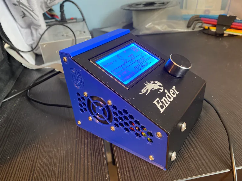
I designed this case to house the Ender 3's LCD unit and Raspberry Pi 4B running Octopi when I moved my Ender 3 into an enclosure. The case has mounting space for a 4010 fan to keep the Pi cool and some zip-tie blocks to keep cable secure and tidy.
When time permits I shall be adding versions supporting the Raspberry Pi Zero 2 W and the Raspberry Pi 3B.
Required hardware:
Case
4 x M3x10 screws
4 x M3x12 screws
8 x M3 hex nuts
Ender 3 LCD Fixings
2 x M5x8 screws
2 x M5 hex nuts
Fan
1 x 4010 Fan (5V to run from Raspberry Pi)
- A "Noctua NF-A4x10 5V" is highly recommended for quiet operation.
4 x M3x16 screws
4 x M3 hex nuts
Raspberry Pi
1 x Raspberry Pi 4B (ideally fitted with heatsinks)
4 x M2.5x8 screws
Cable Management
4 x Zip-ties (2.5mm or preferably narrower)
Build Instructions
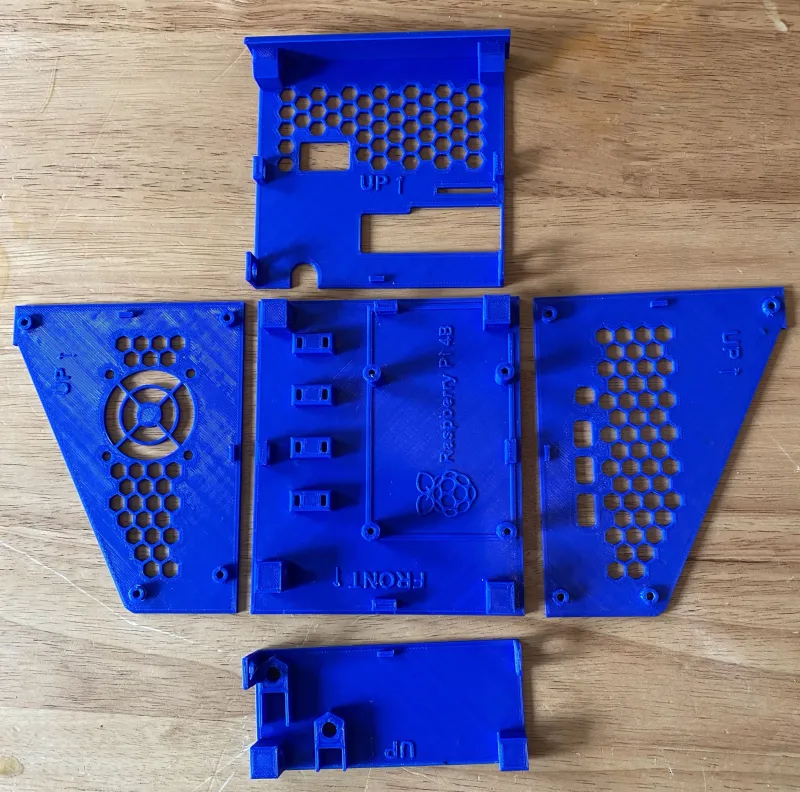
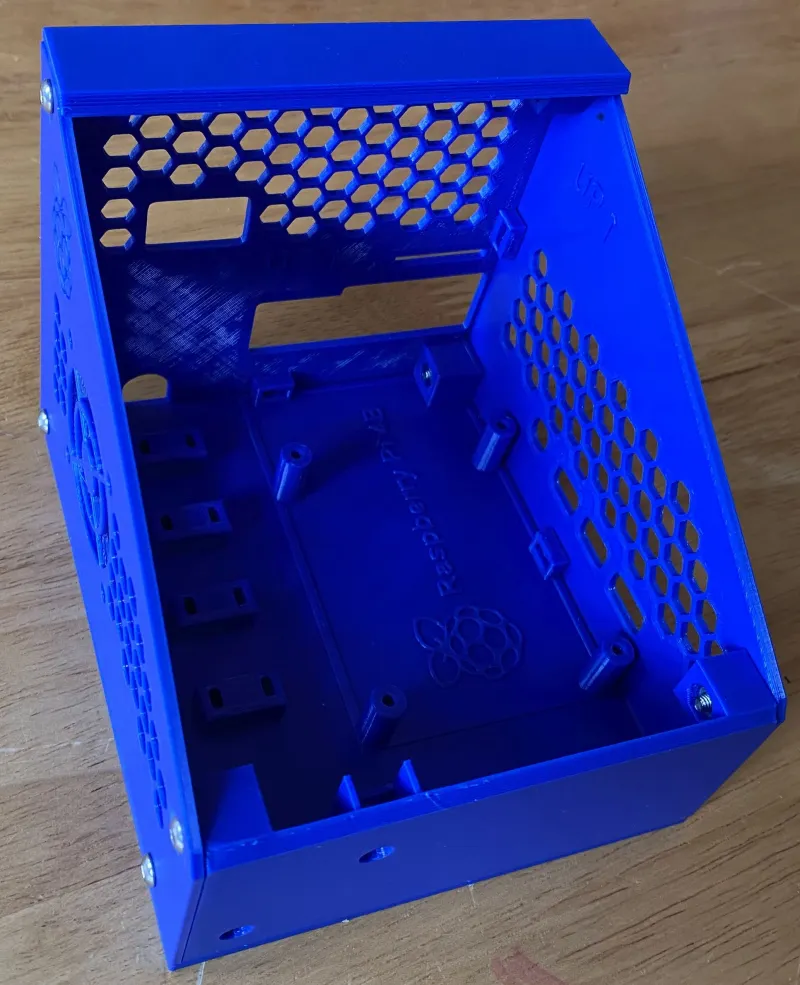
1. Print the base, front back and 2 side parts with a 2mm layer height. I have successfully printed these with PLA, PETG and ABS.
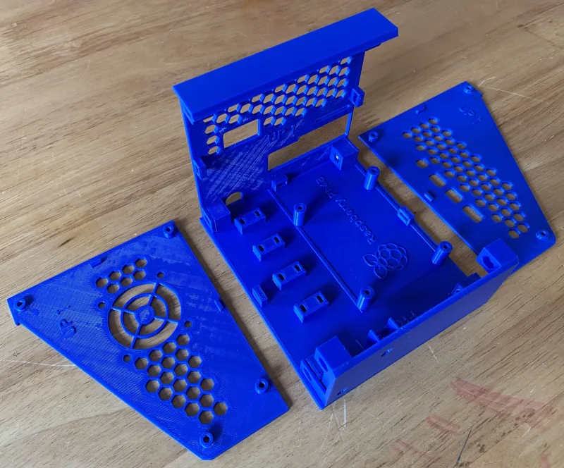
2. Press the front and back pieces firmly onto the base. They should stay in place with just friction for now. Care should be taken as the tabs at the bottom of the back and front panels are delicate before these panels have been fitted to the base.
3. Press the first side piece into place and secure with 2 x M3x12 screws (bottom holes), 2 x M3x10 screws (top holes) and 4 M3 hex nuts.
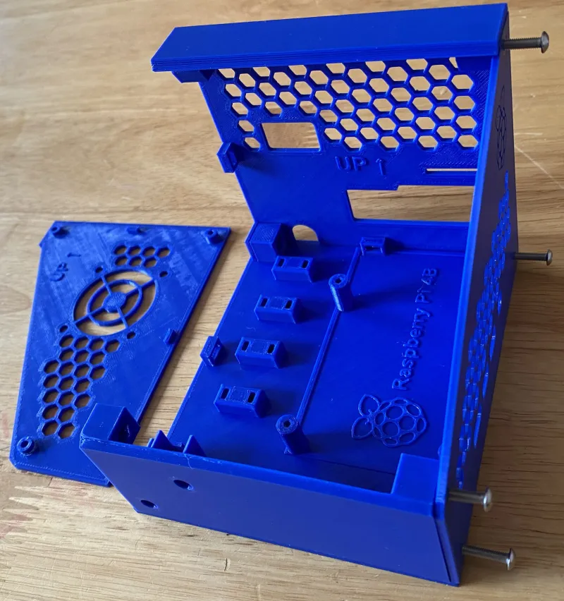
4. Press the second side piece into place and secure with 2 x M3x12 screws (bottom holes), 2 x M3x10 screws (top holes) and 2 M3 hex nuts.
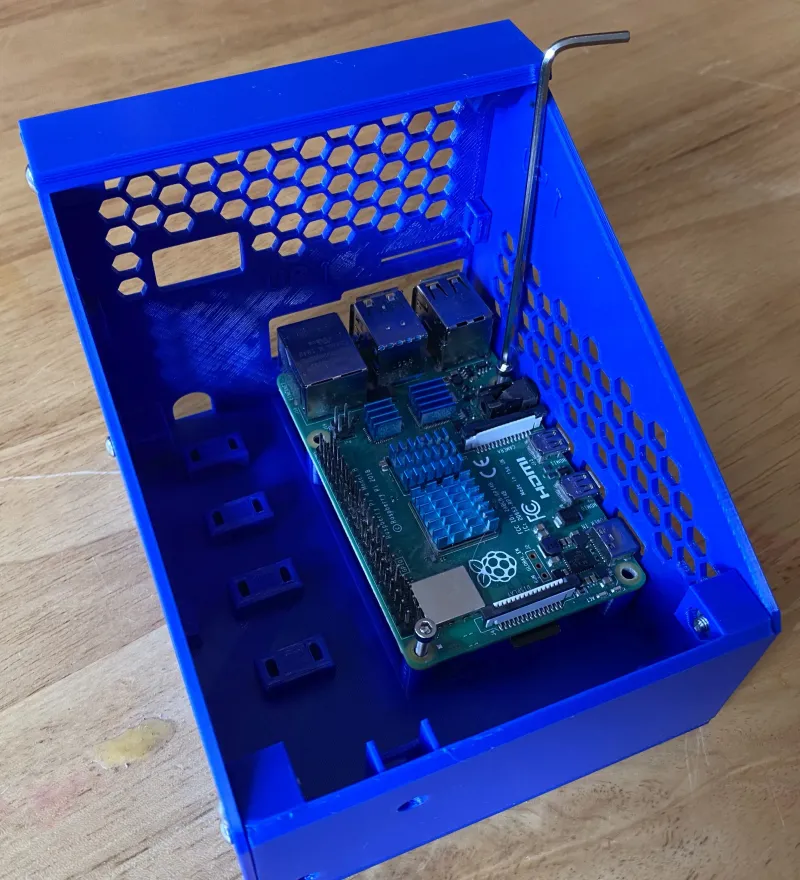
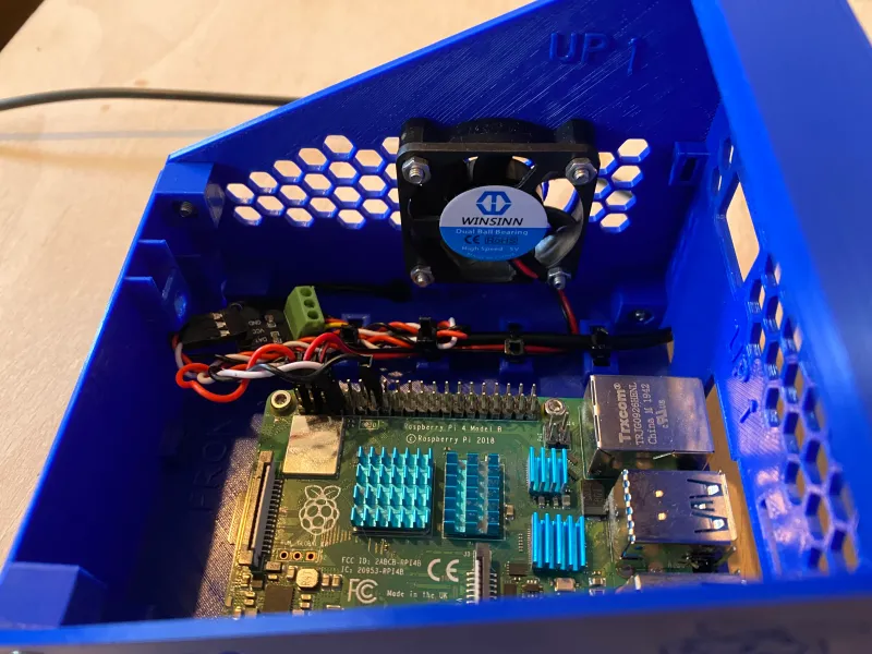
5. Place the Raspberry Pi in position and fix in place using 4 x M2.5x8 screws. There are no nuts used here and the M2.5 screws should self tap into the plastic of the Pi support pillars.
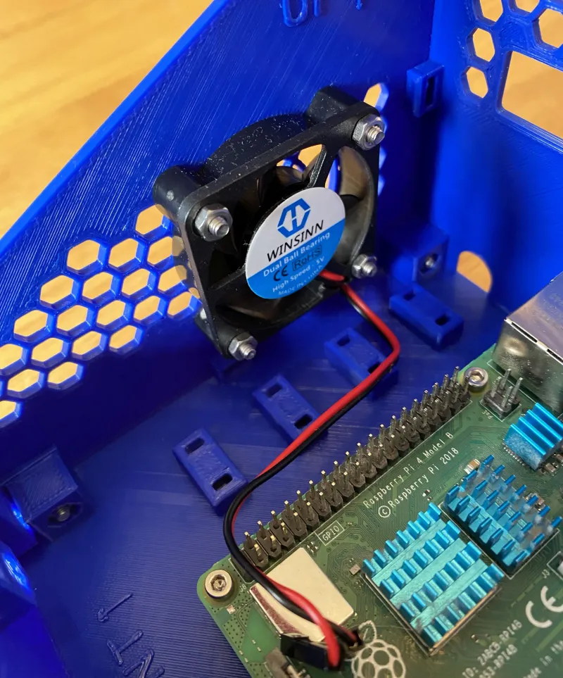
6. Fit the fan to case using 4 x M3x16 screws and nuts.
7. Connect all required wires to the Pi's expansion connector and power the unit to test everything is working as expected - much easier to correct at this stage! In the photo below a DB18B20 Temperature Sensor Module has been connected for monitoring the temperature in the printer enclosure.
Push the 4 zip-ties into one side of the cable tie blocks until they appear out of the other holes. I have used 2.5mm wide zip-ties as that is what I had to hand but narrower ones are available and recommended.
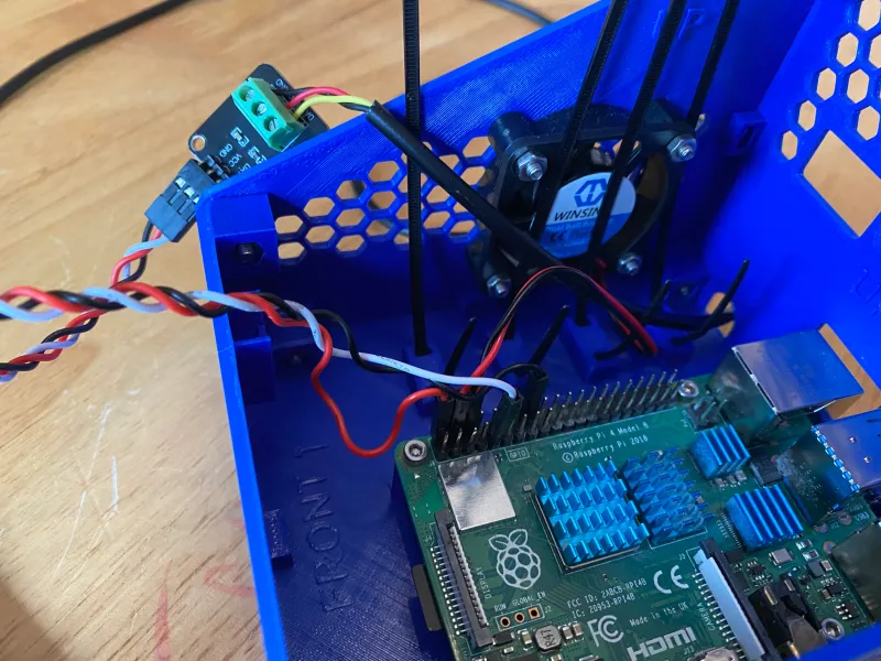
8. Arrange the cables as neatly as possible, tighten the zip-ties and cut off the excess zip-tie length. For me this was enough to hold the temperature sensor module securely in place.
9. If you are using a Raspberry Pi camera that connects with a ribbon cable this is the time to feed it through the back of the case and plug it into the Pi.

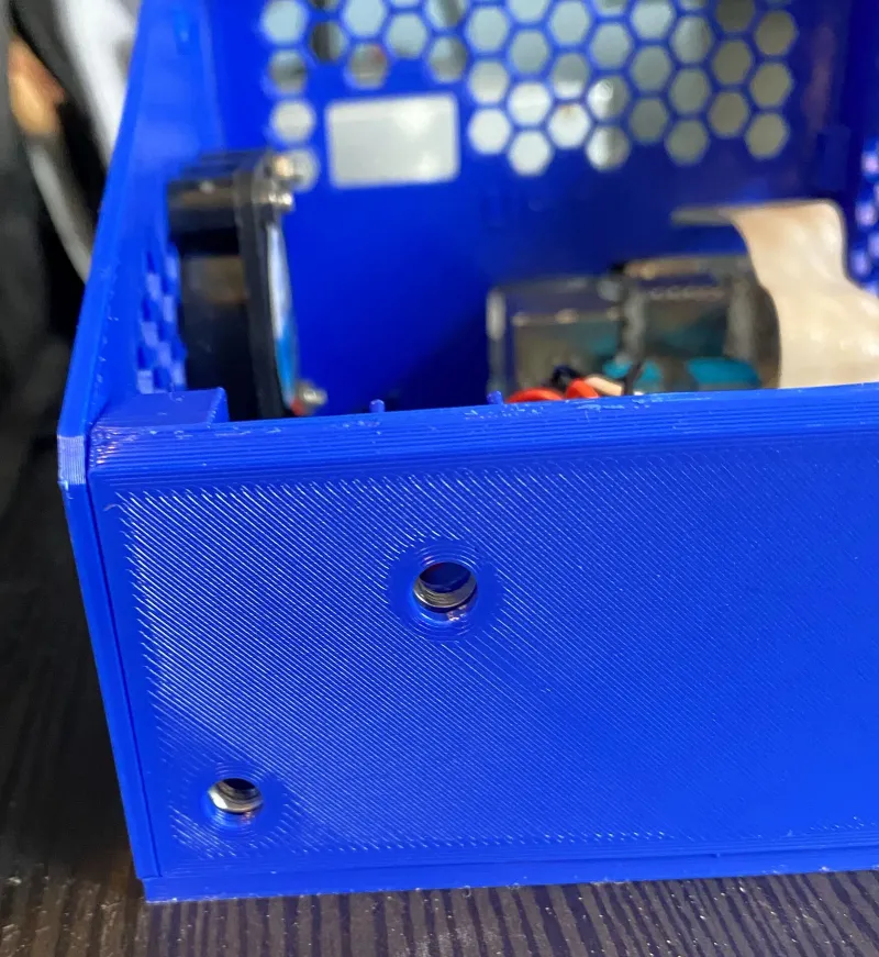
10. Place 2 x M5 nuts in the pockets on the inside of the front panel that the LCD panel will screw into.
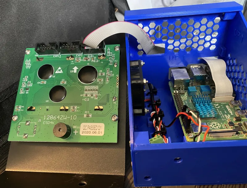
11. Feed the LCD cable through the hole in the back panel and plug into the correct connector in the LCD PCB.
12. Put the LCD unit into place and fix in place with 2 x M5x8 screws.
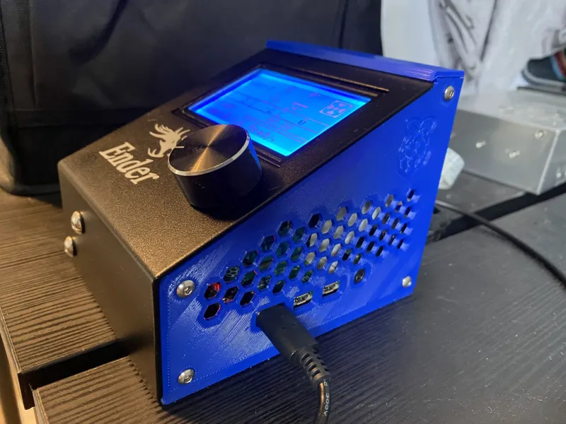
The build is complete!
Model origin
The author marked this model as their own original creation.