Gosainthan, Competition RC Rock Crawler (Super Class) OpenRC


Description
PDFTHIS PROJECT IS STILL ON PROGRESS, WILL BE UPDATED PERIODICALLY.
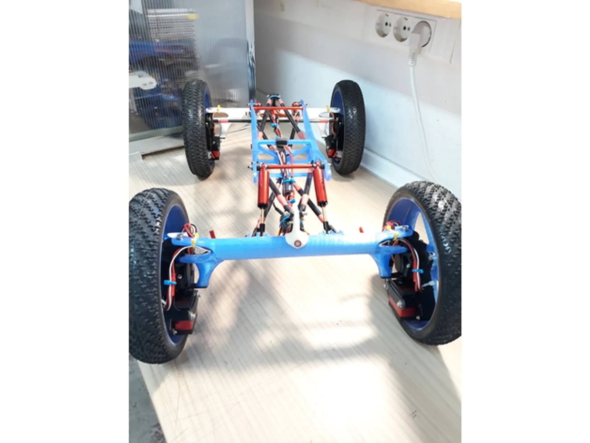
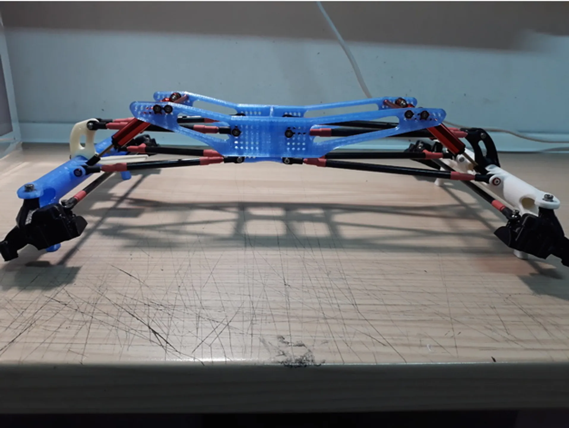
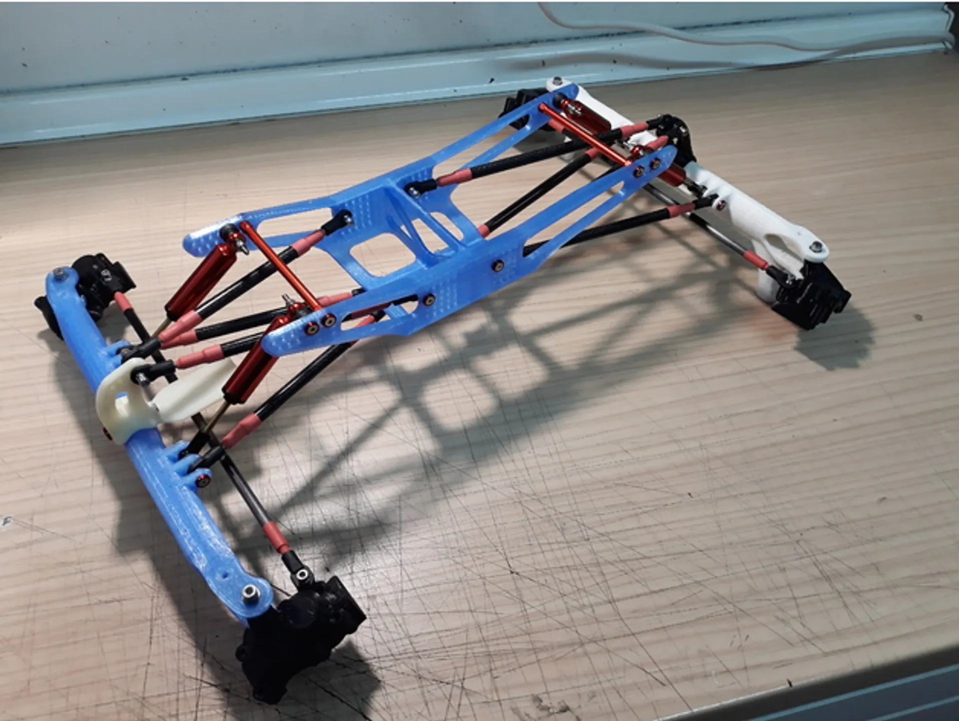
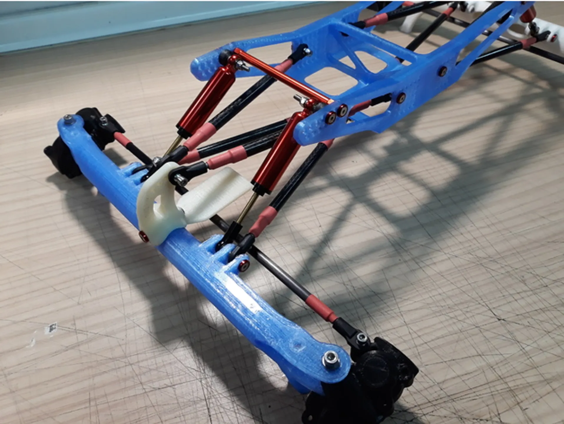
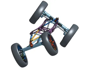
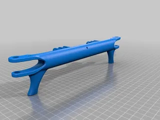
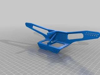
This is the design of a Competition RC Rock Crawler for the Super Class competition category.
This kind of RC cars are not designed for speed they are designed to climb over obstacles (usually rocks) remarkably well and manny times very surprising. You can see how they perform in this video:
You can find more information about this kind of RC cars and competitions in this forum:
http://www.rccrawler.com
You can download the competition rules where the different categories (Clases) are defined and how the competitions go from here:
https://docs.google.com/document/d/1LWjbpH_yxB0n_0F3WMOmRx4DMo_LsBE-DuquBto_nok/edit
SOME HIGHLIGHTS ABOUT THIS KIND OF VEHICLES:
- The superclass category is provably the most technically advanced of the RC crawlers.
- Manny of characteristics of a Rock-Crawler are very different than from a speed-racing car.
- Vehicle weight should be as low as possible.
- CG should be as low and forward as posible. In order to achieve that CG position weights are installed on the front wheels.
- As much suspended mass the better.
- As much turning radius the better.
- Brushless motors are not well suited for the task unless they are sensored (difficult to find)
- Suspensions work more like a energy reservoirs systems for climbing than a normal car suspension.
- On a Superclass both axles are able to steer.
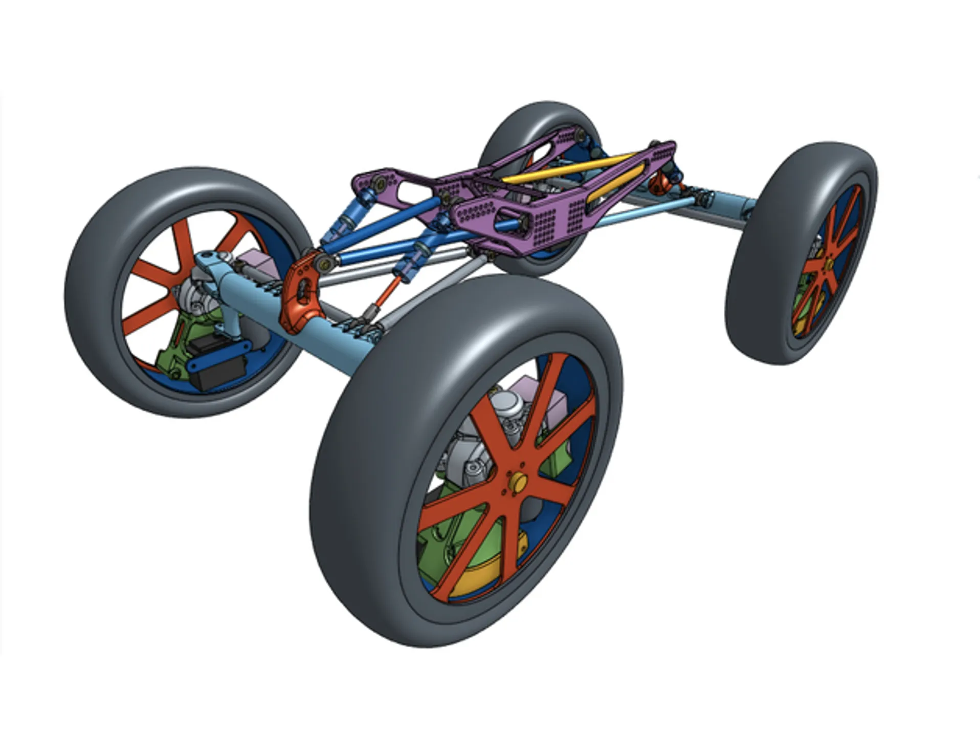
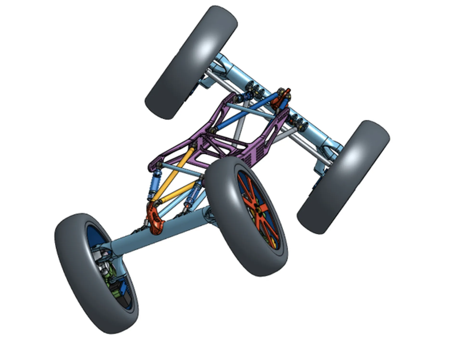
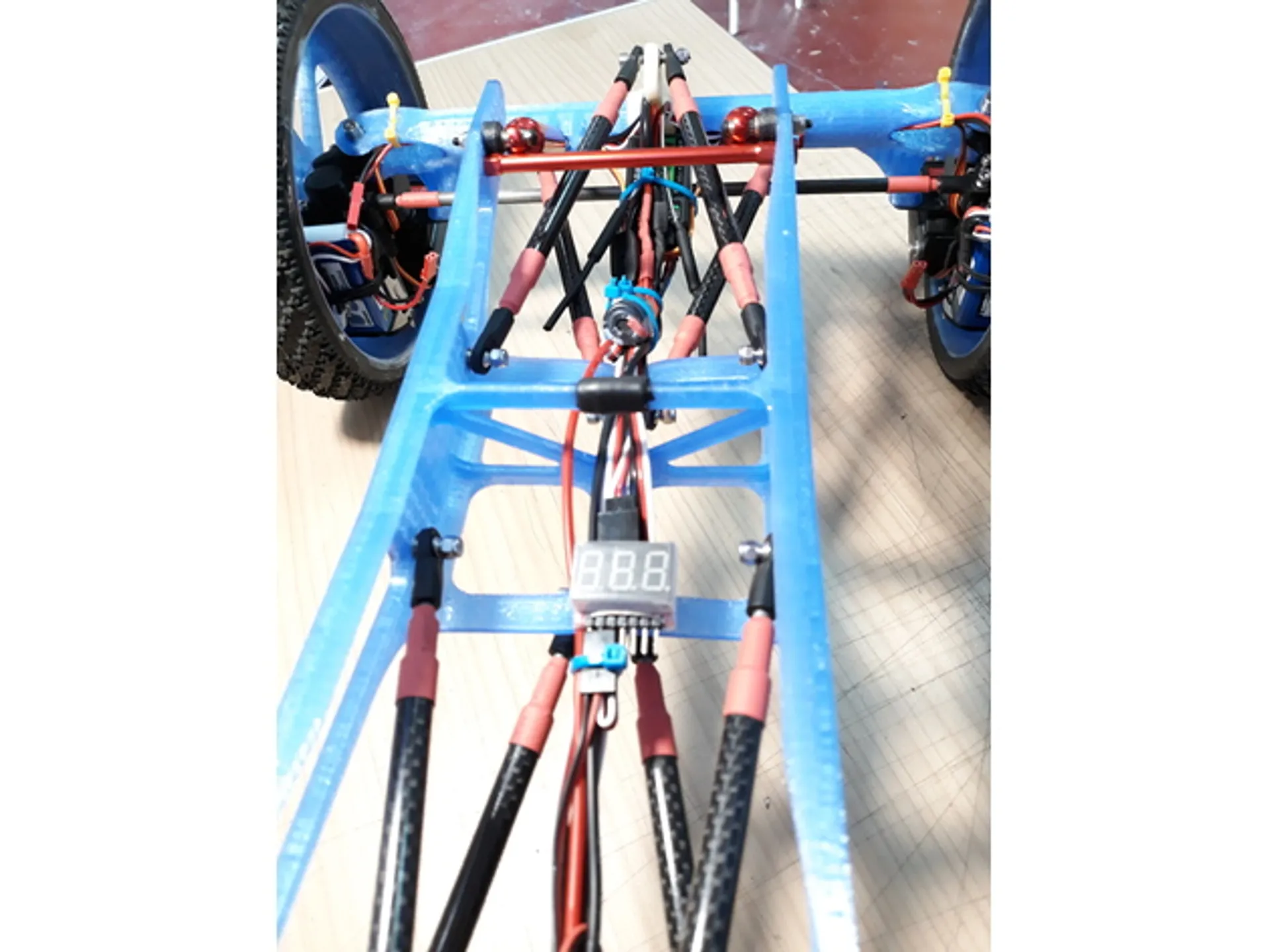
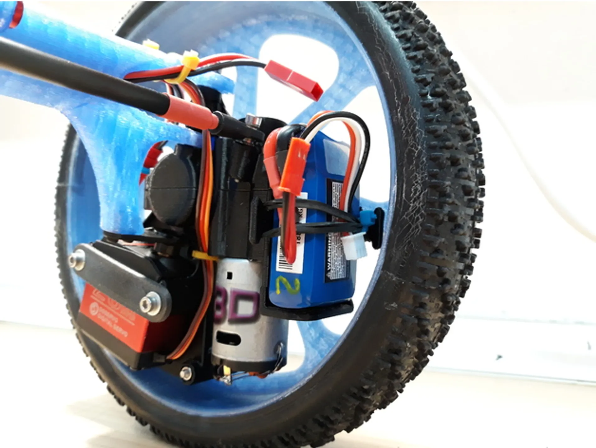
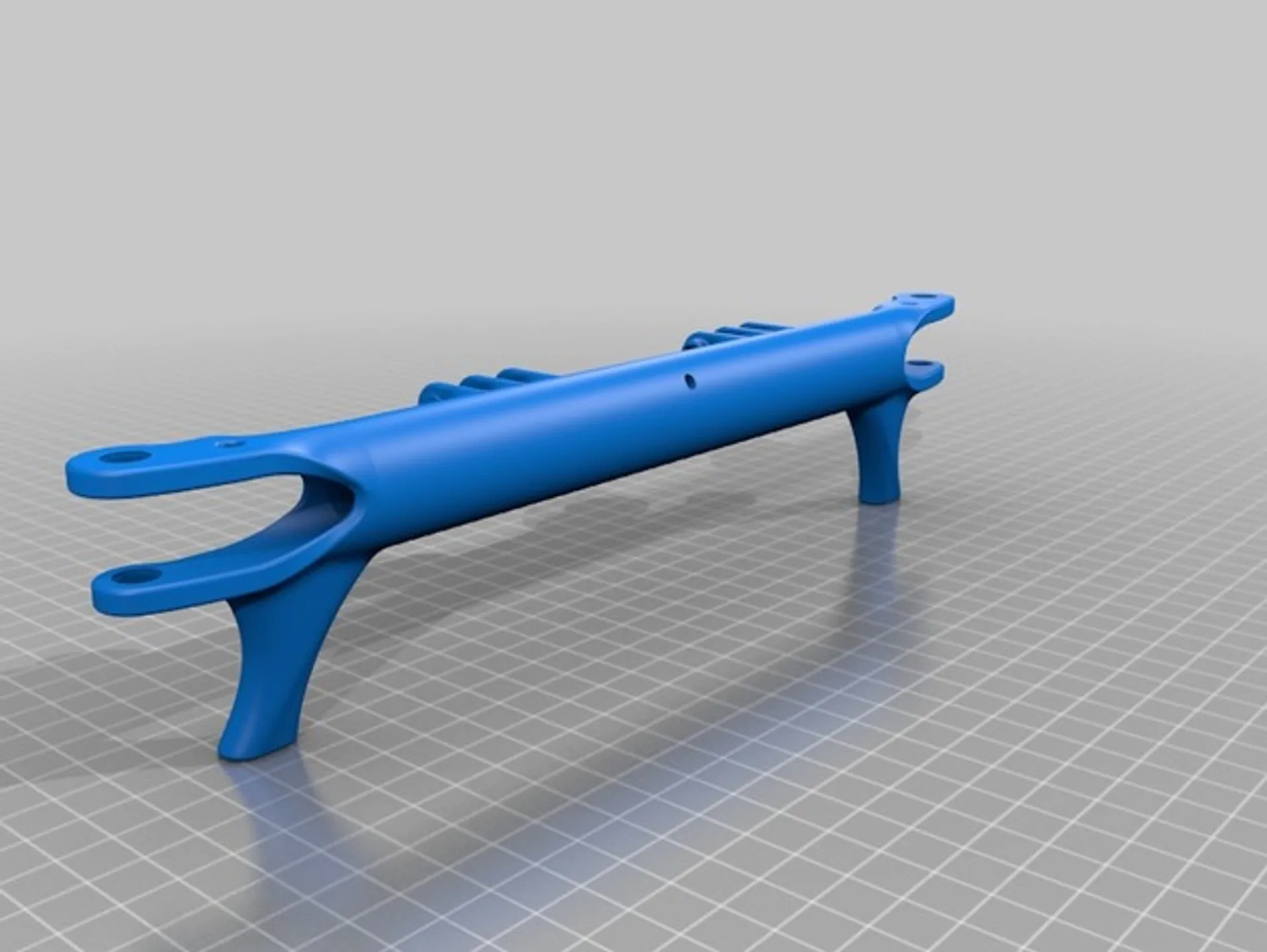
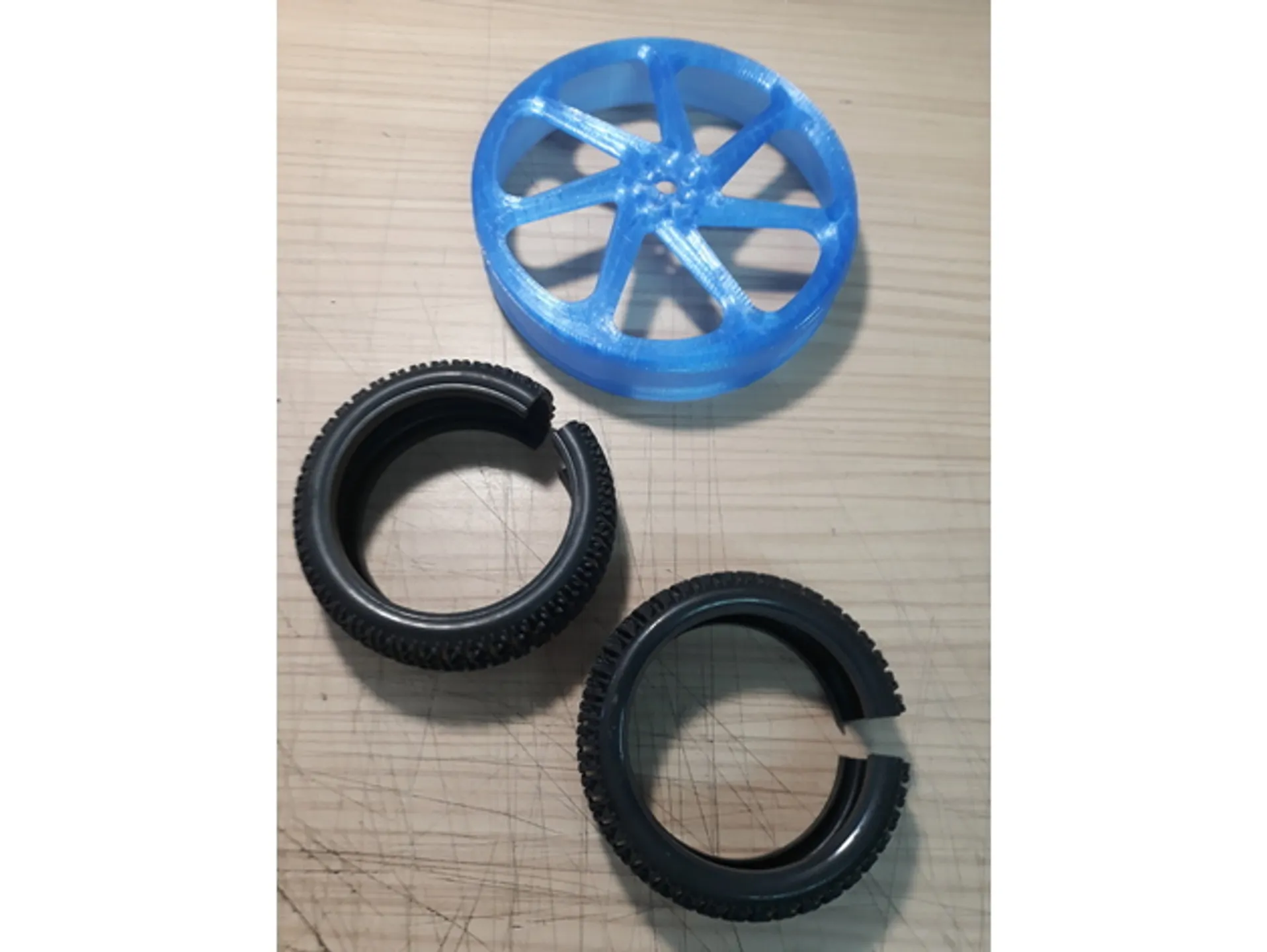
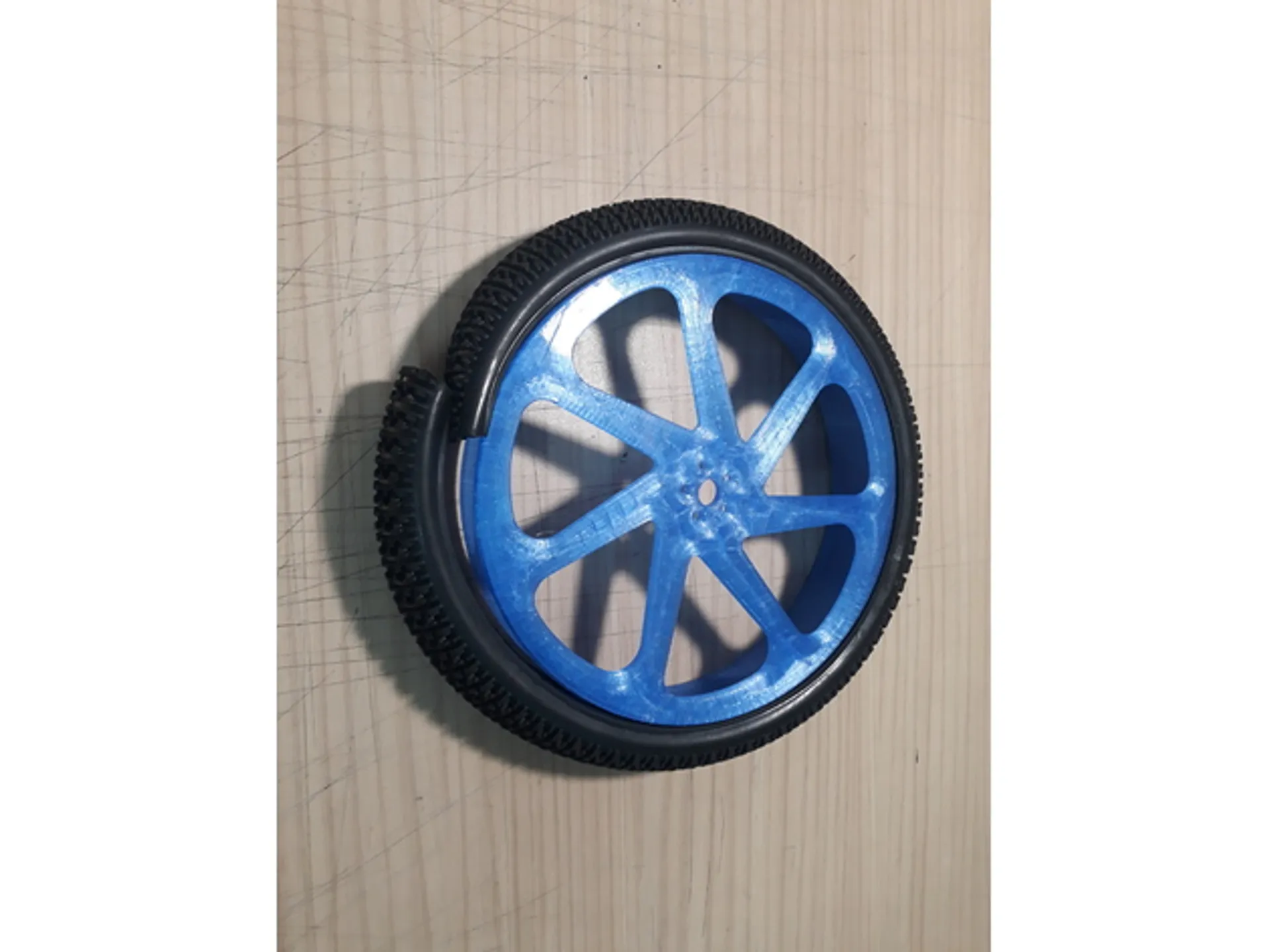
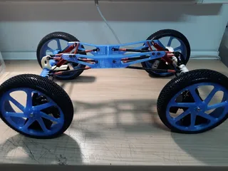
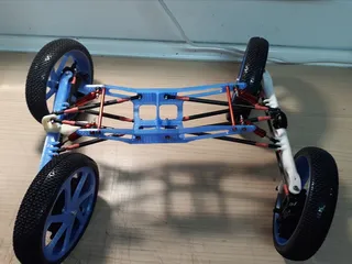
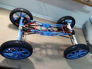
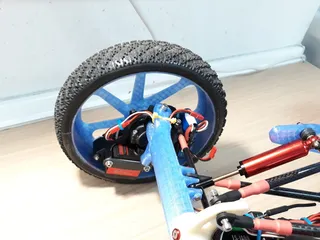
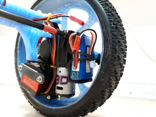
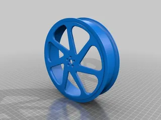
So in order to meet those parameters I come up with this design/idea of how to install all equipment (most of the weight) inside of the wheel rim.
ABOUT ITS DESIGN:
You can access to the CAD files of this project here:
https://cad.onshape.com/documents/27bacf61b020beec43556ddc/w/e8cdb36f8c358f6e6ad41942/e/4e156028111cbb92cec77030
You can see the design just clicking on the link.
You need and Onshape account (it is free) in order to be able to copy, modify, export, etc. the design.
The CAD file will change and improve as time passes, it is more tested and ideas from others are added to the design.
You can find more information on the design, characteristics, and group discussion in this forum thread:
http://www.rccrawler.com/forum/superclass-crawlers/594046-crazy-axles-idea-design.html
SOME NOTES:
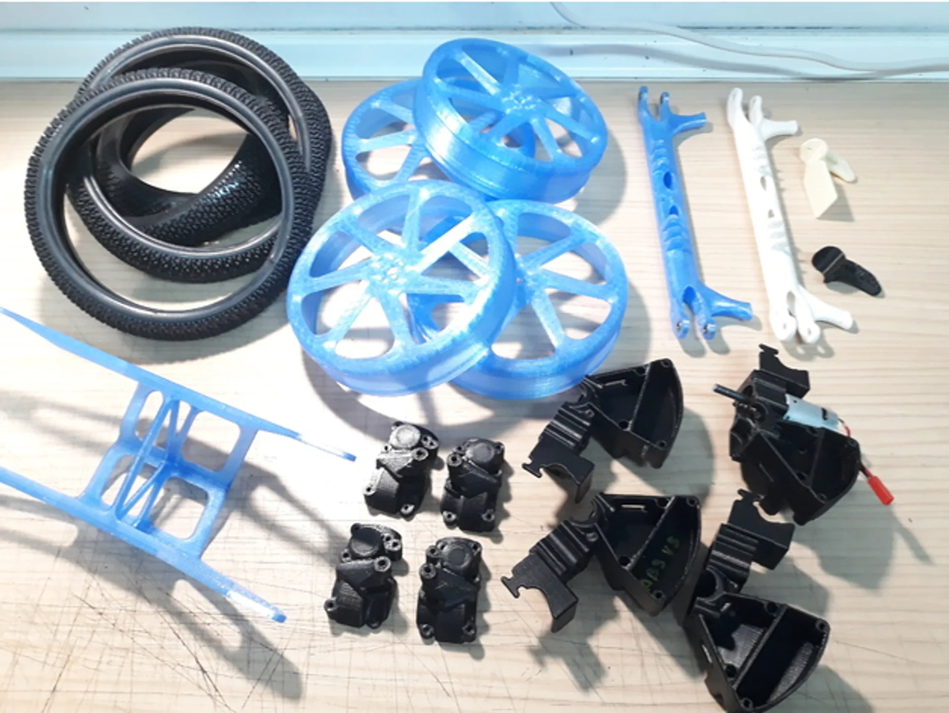
- Some parts can be printed or CNC cut on Glass Fiber, Carbon Fiber or Alum. plate.
- Some parts have to be made on Aluminium or Steel with a lathe.
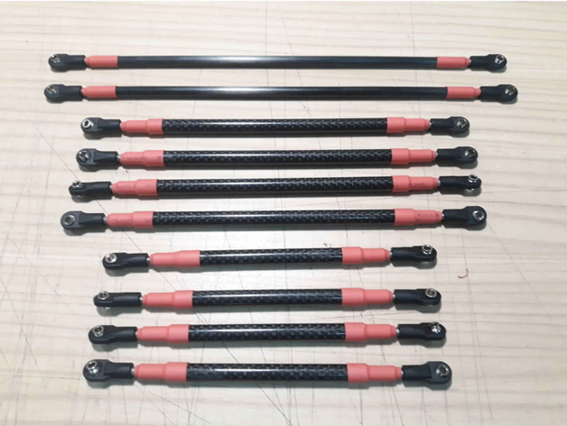
- The steering and suspension links can be made from different materials, CF tube, GF tube, Alum. bar, Steel tube, Ti Tube, etc.
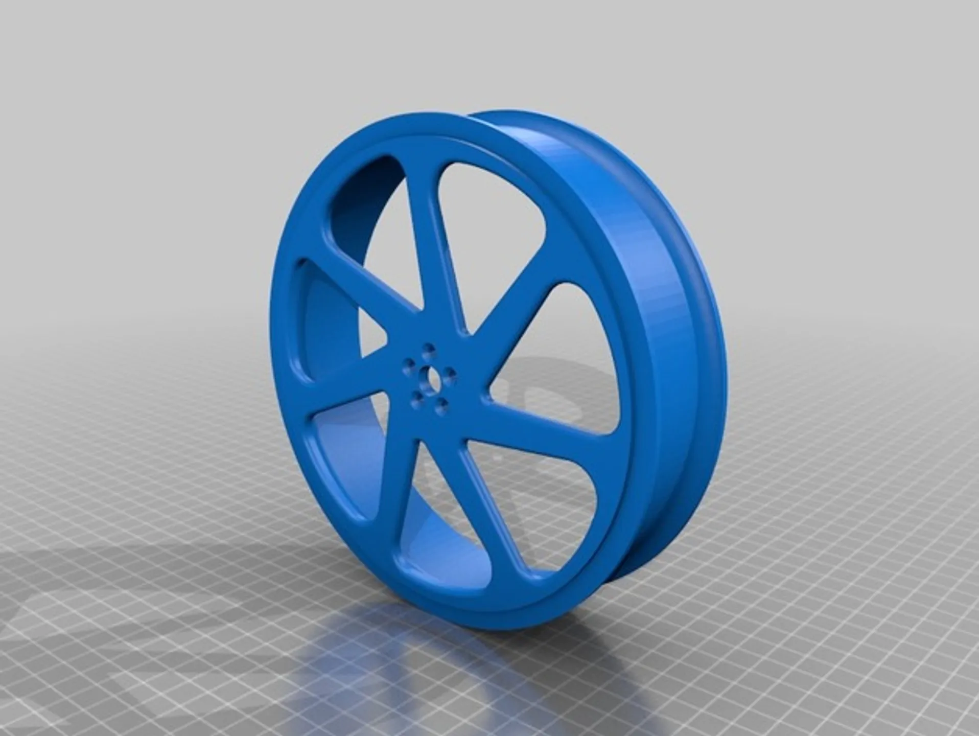
- There is 4 different wheels rims to choose from depending what tire you want to use and how you want to make them (CNC or 3Dprint)
- There is two versions of the chassis on the CAD: V1 Gosainthan and V2 Gasherbrum. (V2 version is not finished or tested).
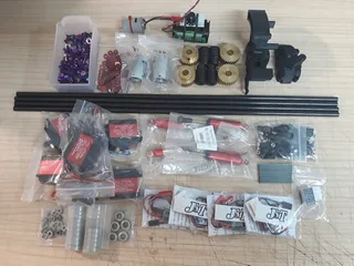
EQUIPMENT SUGGESTED (The links are just suggestions, there can be other compatible options):
- 4 x 380/385 brushed motors
380SA-3065-55 https://www.aliexpress.com/item/1PCS-Car-ship-Model-motor-380SA-3065-55-6-11V-small-electric-drill-motor-2-3MM/32847454353.html?spm=a2g0s.9042311.0.0.168b4c4d7gABNr - 4 x 20-25A Motor Speed Controllers with reverse function
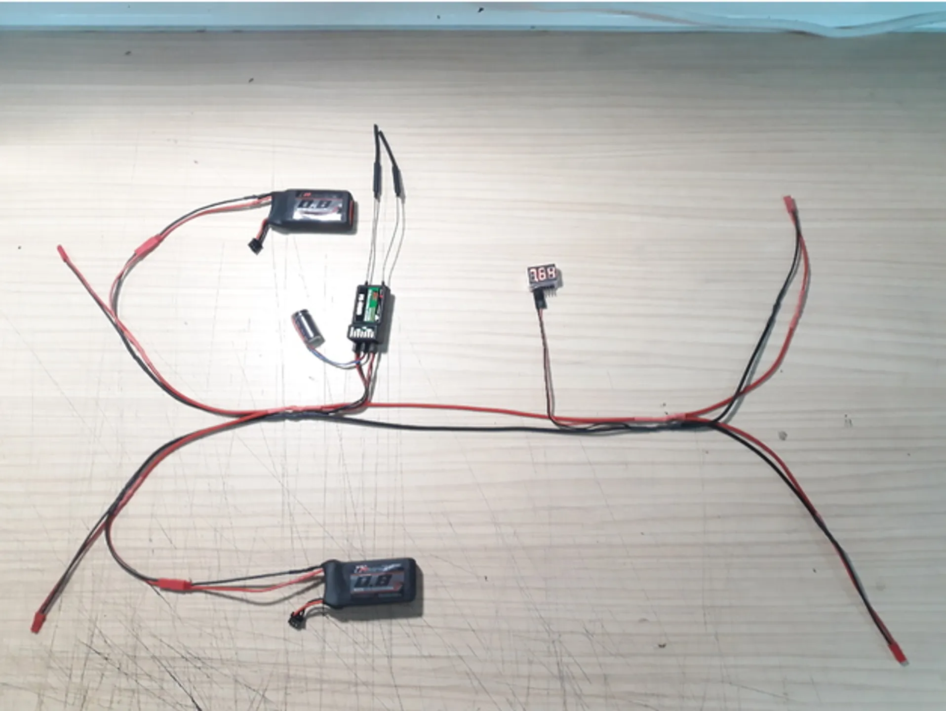
JMT 20A Brushed ESC https://www.aliexpress.com/item/JMT-20A-Brushed-ESC-Car-Motor-Speed-Controller-Bothway-No-brake-function-For-1-16-1/32766637613.html?spm=2114.13010708.0.0.73b94c4dwuB975 - 2 x 7.4V (2S) 750-850mAh Lipo batteries (one on each front wheel)
800mAh 2S https://hobbyking.com/en_us/turnigy-800mah-2s-40c-lipo-pack.html - 4 x 15-25Kg/cm 180º or 270º Standard size servos
DS3218 or DS3120 https://www.aliexpress.com/item/5pcs-lot-20kg-RC-Servo-Waterproof-Aluminum-Shell-Servo-Metal-Gear-Digital-Servo-Baja-Servo-For/32832143326.html?spm=2114.13010708.0.0.73b94c4dwuB975 - 1 x 6+ Chanels Receiver + 1 x 6+ Programable Transmitter
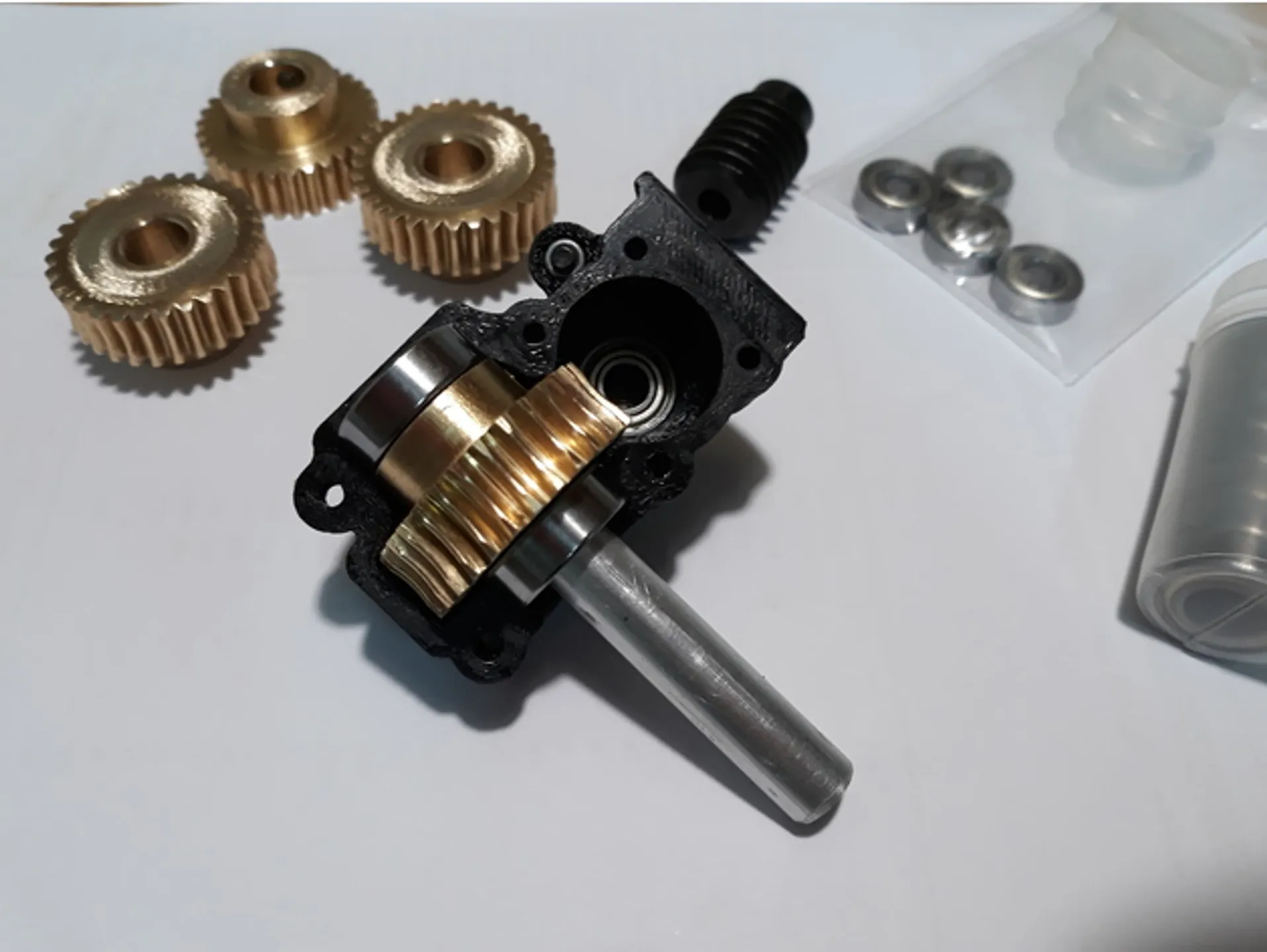
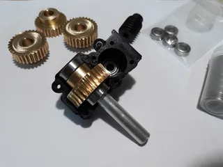
Flysky FS-i6X https://www.aliexpress.com/item/Flysky-FS-i6X-2-4GHz-6CH-AFHDS-2A-RC-Transmitter-with-FS-iA6B-Receiver-FS-I6X/32840184468.html?spm=2114.13010708.0.0.3a994c4d25zFcZ - 4 x Worm gear sets 30:1
1M-30T reduction ratio: 1:30 copper worm gear model A https://www.aliexpress.com/item/Free-shipping-1M-30T-reduction-ratio-1-30-copper-worm-gear-reducer-transmission-parts-gear-hole/32517750717.html?spm=2114.13010708.0.0.3a994c4deod5cN - 20 x Ball rod end bearings
A2 Straight plastic https://www.aliexpress.com/item/Free-Shipping-10Pcs-length-19-27mm-Bending-18-Straight-M3-ball-head-hole-Rod-End-Buckle/32680854552.html?spm=2114.13010708.0.0.3a994c4d5CXREa - Carbon tube
8x6mm tube https://www.aliexpress.com/item/TianYuQi-3k-100-full-Carbon-fiber-circular-tube-500mm-Length-OD-10mm-12mm-14mm-15mm-16mm/32815243370.html?spm=2114.13010708.0.0.3a994c4d5CXREa - 4 x 90 to 110mm Shock absorbers
100mm Shock absorbers https://www.aliexpress.com/item/AXSPEED-4-PCS-lot-100mm-Axial-SCX10-D90-SUSPENSION-SHOCKS-SHOCKS-ABSORBER-100MM-RED-Blue-Green/32804872230.html?spm=2114.13010708.0.0.3a994c4d5CXREa - 2 x 90mm stands off
90mm stands off https://www.aliexpress.com/item/2pcs-lot-Lightweight-aluminum-hexagonal-column-M3x50mm-M3x60mm-M3x70mm-M3x80mm-M3x90mm-M3x100mm-flight-models/32837303726.html?spm=2114.13010708.0.0.3a994c4d5CXREa - 12 x Motors capacitors
- 1 x Capacitors array
- Tires
- Bearings
- Screws, nuts, washers.
PENDING UPDATES:
- To finish BOM and links to possible suppliers
- Assembly instructions
- Transmitter programming and mixes
- More pictures and action videos
UPDATES LOG:
6/2/2018
- Added an Updates Log
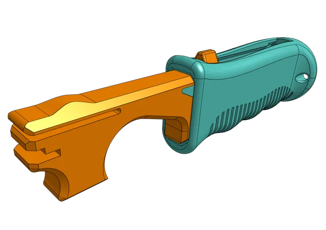
- Added Calibration Cube
Holes on the L side are Loose fit for a 3mm screw
Holes on the T side are Tight fit for a 3mm screw
A 3mm nut should enter on the hexagon holes
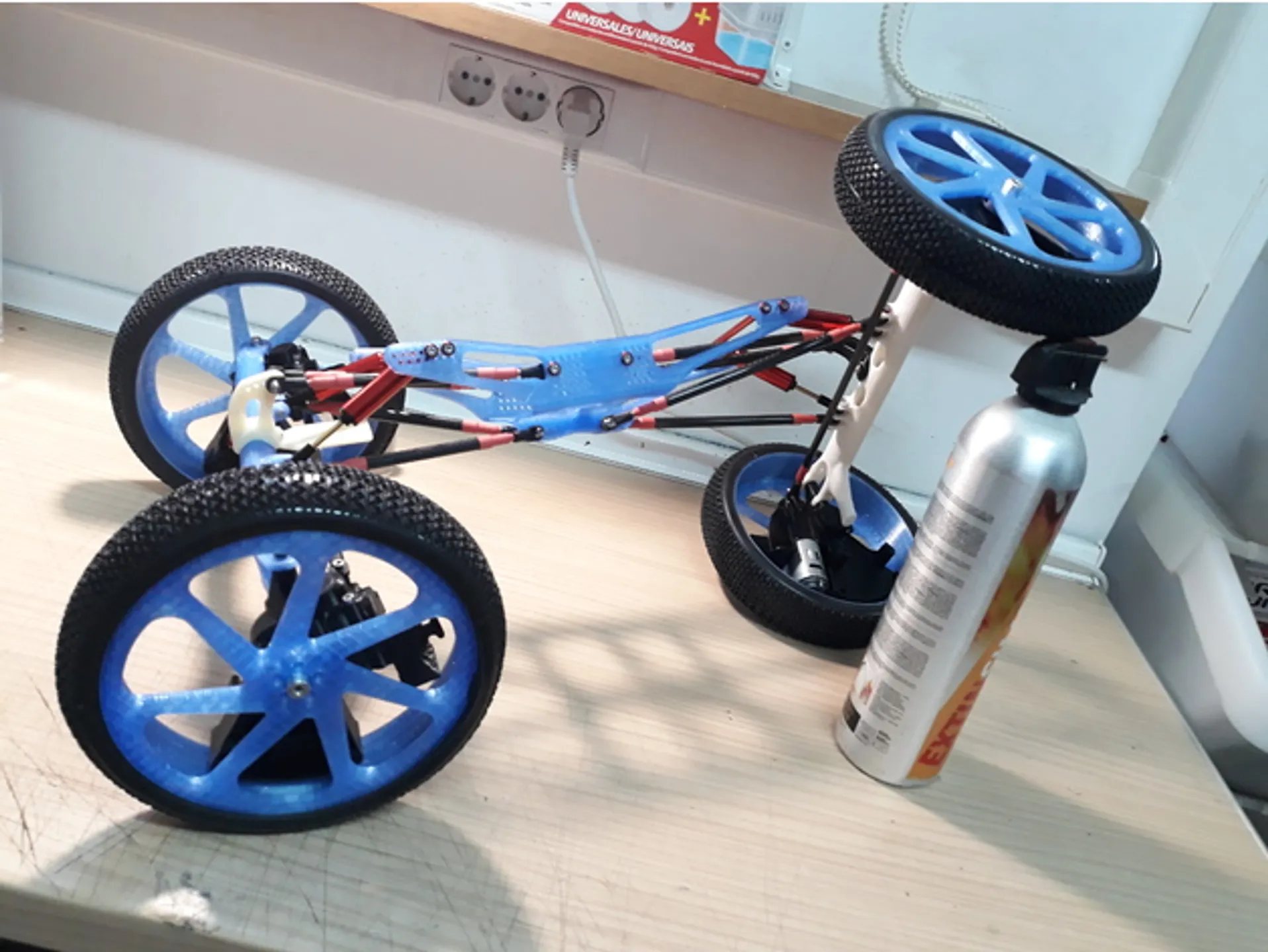
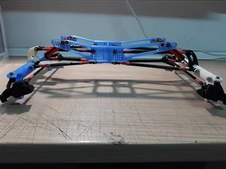
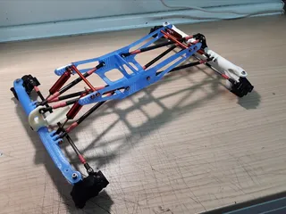
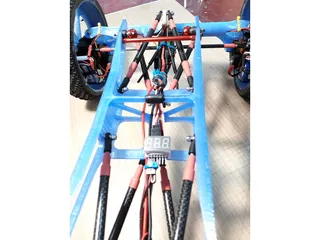
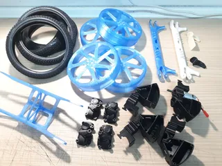
6/10/2018
- Added pictures of final assembly
6/15/2018
- Video of first runs: https://youtu.be/hZ67wPU9bRE
Maneuverability is great, even that I am not getting full turning radius with this servos.
But it does not work any well due not using the correct gears and not appropriate gear ratio. It almost has no power due that.
New gears are on the way - Removed PETG as recommended material for this project due its viscoelasticity
It can cracks when sudden forces are applied, i.e. in a crash
11/17/2018
- Corrected typos. Thank you @danjr1
4/6/2020
- Texts revised, and sightly modified and updated.
- Project added to Prusaprinters page.
Print instructions
- Recommended materials:ABS, PC, Nylon, High temperature PLA.
- I used Cura slicer.
- Print with walls and top/bottom thickness of around 1.5mm to 2mm
- Recommended nozzle size 0.4 to 0.5mm
- Recommended layer high 0.15 to 0.25mm
- Recommended print line width of 120% to 150% of nozzle diameter.
- Infill 15-20%
- Recommended to add "Alternate extra wall" in order to improve strength.
- Tolerances for the screws, gears and other parts are included on the design. But you have to make sure that print comes out accurate so all parts will mount together properly. So in some printers or with some materials it is necessary to adjust the horizontal expansion usually around -0.1 to -0.2mm
- Retraction minimum travel 5mm to 6mm
- Recommended to increase printing temperature in order to get good layer adhesion.
- Recommended to decrease printing speed in order to get good layer adhesion and accuracy.
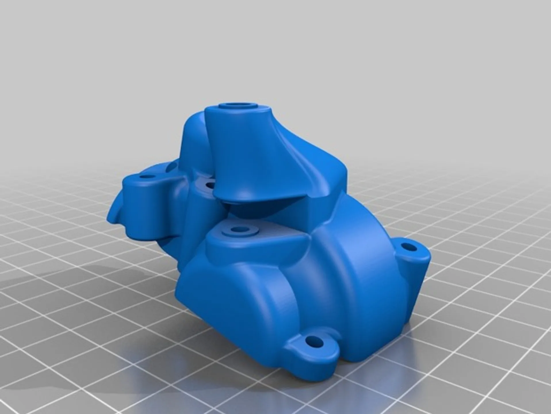
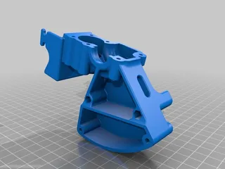
- Wheel rims, Details, Gearbox cover, and Gearbox servo holder do not need support. all the other parts need support.
- Maker sure to realign the flat faces of the parts to the bed on the slicer.
- Make sure the parts are touching the bed on the slicer.
- Axle spurs recommended to be printed horizontal instead of vertically.
Post-Printing
Remove supports and brims on the parts printed with them.
Some screw holes may need to be trimmed.
Tags
Model origin
The author hasn't provided the model origin yet.